TM 1-5855-265-20
3-43
3-11. PNVS TURRET ASSEMBLY REMOVAL (cont)
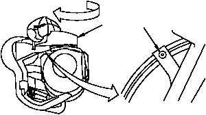
11. Move PNVS turret assembly (24) again to get
to third captive mounting screw (29). Move
PNVS turret assembly, step 7 above. The
third screw (29) will come into view after two
more gear cutouts (30) have passed (about
65º of PNVS turret assembly rotation).
12. Loosen captive mounting screw (29). After
loosening screw, make sure it hangs freely.
13. Move PNVS turret assembly (24) again to get
to fourth captive mounting screw (31). Move
PNVS turret assembly, step 7 above. The
fourth screw (31) will come into view just
before PNVS turret assembly stops turning.
14. Loosen captive mounting screw (31). After
loosening screw, make sure it hangs freely.
15. Move TADS turret assembly (para 3-4)
another 90° in direction shown by arrow. This
provides work space behind left side of TADS
turret assembly.
TURN
24
30
29
310-005A
TURN
24
31
310-006
TURN
310-007
TADS TURRET
ASSEMBLY