TM 1-5855-265-20
3-39
3-11. PNVS TURRET ASSEMBLY REMOVAL
INITIAL SETUP
Tools
Aircraft armament repairman tool set
Maintenance platform (optional)
PNVS turret assembly holding fixture
Personnel Required
68X Aircraft Armament/Electrical Repairer (2)
One person to assist
References
TM 1-5855-265-T
Equipment Conditions
Ref
Condition
Para 3-4
TADS turret assembly
135° out of stow
Para 3-9
PNVS window cover
assembly installed
NOTE
If replacing PNVS turret assembly because
shroud window is broken, you must salvage
the pieces of window. Observe precaution on
broken infrared optical glass in TM 1-5855-
265-T. Put pieces of window in suitable
container and ship it with the faulty PNVS
turret assembly.
CAUTION
PNVS window cover assembly must be
installed before starting this task. Optical
coating on window could be damaged if PNVS
window assembly cover is not installed.
NOTE
PNVS cables which have been modified to add
EMI shielding have one tiedown strap. Cables
which have not been modified have two
tiedown straps.
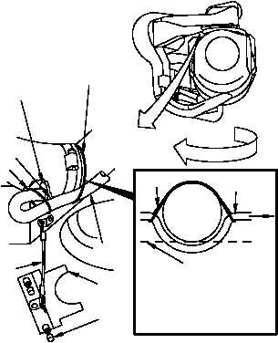
1. Cut tiedown straps (1).
2. Remove seal access cover (3).
a. Loosen two captive screws (2) on seal
access cover (3).
b. Remove access cover (3) from rubber seal
(4) on cable (5). Let cover hang by its
attached wire rope (6).
3. Push seal (4) through hole (7).
1
4
7
6
3
2
5
TURN
310-051B
1
AIR DUCT
BOTTOM OF
W10
DUCT
AIR
P1
NOTE:
BOTTOM OF CABLE AT
TIE POINTS SHOULD BE
ABOVE BOTTOM OF AIR
DUCT.
1


