15. Use a razor knife to remove any frayed hel-
met fibers resulting from drilling.
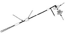
16. Referring to Figure 4-12.3, View, A, slide the
large black spacer over the wires of the inter-
face harness and onto the connector.
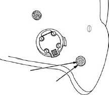
17. From outside the helmet, insert the black and
white wires of the interface harness through
the drilled hole so that the grommet is com-
pletely through hole, the head of the connec-
tor is against the spacer, and the spacer is
against the outside of the helmet as shown
in Figure 4-12.3, View B.
NOTE
The earcup grommet may be difficult to pull
through the helmet shell.
CAUTION
Do not twist the connector. The interface wire
on the back of the connector may
break if you do.
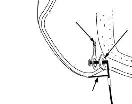
18. From inside the helmet, slide the ground lug
over the wires and onto the connector, fol-
lowed by the nut. Ensure that the unattached
ground wire is pulled through the ground lug
and nut as shown in Figure 4-12.3, View C.
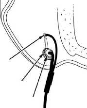
19. Ensure that the ground lug is oriented toward
the crown of the helmet as shown in Figure
4-12.3, View D. Tighten the nut using the
7/16-inch open-end wrench. Ensure that the
nut is tight enough that the ground lug will not
rotate when pushed.
NOTE
In Step 20, ensure that the soldering is per-
formed by qualified personnel, and
in accordance with ANSI/J-STD-001.
20. Using long-nose pliers, carefully bend the
ground lug to about a 45-degree angle from
the shell so that it reaches the unconnected
ground wire. Insert the stripped end of the
unconnected ground wire through the small
hole at the end of the ground lug. Wrap the
exposed part of the wire once around the
end of the ground lug. Solder the wire.
Bend the ground lug flush with the inside
surface of the helmet shell.
Figure 4-12.3. Connector Installation
VIEW A
VIEW C
(INSIDE
HELMET)
VIEW D
(INSIDE
HELMET)
INTERFACE
HARNESS
SPACER
CONNECTOR
EARCUP
GROMMET
VIEW B
(OUTSIDE
HELMET)
CONNECTOR
SPACER
GROUND LUG
NUT
UNATTACHED GROUND WIRE
WIRE TO BE
SOLDERED
GROUND LUG
NUT
Change 3
4-18.3
TM 1-8415-216-12&P