CAUTION
In Step 9, use only rosin core solder
when soldering the wires.
NOTE
In Step 9, ensure that the soldering is
performed by qualified personnel, and
in accordance with ANSI/J-STD-001.
9. Solder the hook and the exposed wire
to form a single junction.
10. Repeat Steps 6-9 to connect the white
lead of the interface harness to the
white lead of the communications cord.
NOTE
The receiver is not polarized. In Step
11, the white and black leads can be
attached to the receiver either way.
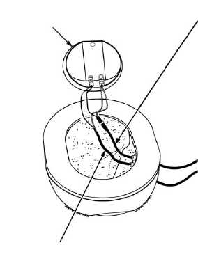
11. Using a jeweler’s screwdriver, reattach
the receiver. Figure 4-12.6 shows the
completed connection.
12. From outside the earcup, carefully pull the excess wire from the communications cord
and the interface harness back through the grommets, being careful not to pull the
CEP interface cable beyond the point at which the shrink tubing touches the grommet.
13. Insert the filler pad, the receiver, and the receiver retainer back into the earcup, and
reinstall the earseal. Refer to Figure 4-12.1 for proper order of parts.
14. Route the earcup with the interface harness through the retention assembly using the
same path that it originally followed.
15. Reattach the earcup to the earcup retainer pad in its original position.
16. Route excess cable between the energy-absorbing liner and the helmet shell, being
careful not to damage the cable or the liner.
17. Plug CEP into the jack in the helmet and the communications cord into the
intercommunications unit and check for proper operation of the CEP and the
receivers.
c. Checking Earcup Fit
1. Have the user don the helmet.
2. Check the earcup fit, ensuring that the ears are properly centered in the earcups.
Adjust the earcups if necessary in the same way as with the standard HGU-56/P.
Figure 4-12.6. Earcup Reassembly
INTERFACE HARNESS
COMMUNICATIONS CORD
RECEIVER
Change 3
4-18.5/(4-18.6 blank)
TM 1-8415-216-12&P