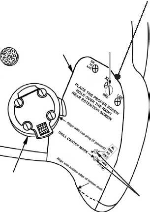
7. Position the helmet so that the right
rear side is facing you.
8. Check the size of the helmet.
9. Depending upon the helmet size,
position one of the four large holes
along the top of the template over
the right rear retention screw
(located next to the eardome) as
in Figure 4-12.2.
NOTE
Ensure that the template follows the
contour of the helmet shell.
10. Align the curve at the bottom of the
template with the helmet shell edge
beading. If the helmet has a cap
plug, align the curve on the left side
of the template with the cap plug.
11. Depending upon the helmet size,
select the hole to be drilled. Using a
pencil or an awl, mark the location
of the hole to be drilled, in the shell,
through the template hole labeled
DRILL CENTER MARK. Ensure
that the mark is located on the bend
in the shell along the edge of the
eardome and is approximately 1
inch above the edge of the helmet
shell.
WARNING
When the helmet shell is drilled in Step 12, the drill bit may penetrate the shell very
quickly. To avoid injury, keep hands away from the inside of the helmet when drilling.
CAUTION
When performing Step 12, hold the drill perpendicular to the helmet shell to prevent
damage to the shell and the energy-absorbing liner.
Ensure that the earcup, the wires, and the retention assembly inside the helmet shell are
away from the area where the hole is to be drilled to prevent damage.
If the helmet shell is not drilled in the following manner, delamination of the shell layers
could occur, making the helmet shell unserviceable.
12. Drill a 1/8-inch hole into the marked location.
13. Drill a 1/4-inch hole into the 1/8-inch hole.
14. Drill a 3/8-inch hole into the 1/4-inch hole.
Figure 4-12.2. Template Placed on Helmet
ONLY
ONE
HOLE
TO BE
DRILLED
PLACE
PROPER
HOLE OVER
RETENTION
SCREW
TEMPLATE
CAP PLUG
BEND TEMPLATE ALONG EDGE OF EARDOME
4-18.2 Change 3
TM 1-8415-216-12&P