TM 1-8415-216-12&P
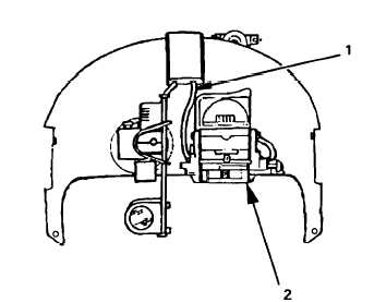
18. install the ANVIS V-2
mount as follows:
(a) Referring to
Figure 4-38,
position the
mount (2) with
its holes aligned
over the holes in
the housing.
(b) Insert four screws
through the hous-
ing and into the
mount.
(c) Route the cable
(1) under the
housing and
through the hole
at the top of the
housing.
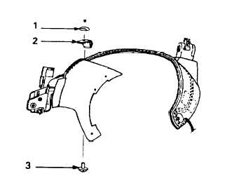
(d) Referring to Figure
4-39, attach the
cable clamp (2)
with the screw (1)
and post (3).
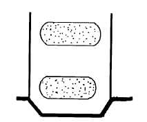
19. Referring to Figure
4-40, install moleskin
patches to cover the
screws on the inside
of the visor housing.
Figure 4-38. ANVIS V-2 Mount Installed
Figure 4-39. Installing ANVIS V-2 Cable Clamp
Figure 4-40. Moleskin Patches Installed
4-40