TM 1-8415-216-12&P
13. Install the connector plug housing onto the cable.
14. QUALIFIED PERSONNEL ONLY: If necessary, cut, strip, and tin the eight
conductor leads.
WARNING
Exercise care when using the soldering gun.
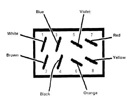
15. QUALIFIED PERSONNEL ONLY: Referring to Figure 4-37, use a soldering gun
(Item 12, Appendix B), soldering flux (Item 8, Appendix E), and tin alloy solder
(Item 18, Appendix E) to solder the conductor leads to the connector terminal in
the following pattern:
Color
White
Brown
Blue
Black
Violet
Orange
Red
Yellow
Terminal
1
2
3
4
5
6
7
8
16. Slide the connector housing over the connector body and install the housing pin.
17. Tighten the two screws in the cable connector clamp.
Figure 4-37. Conductor Lead Pattern
4-39