TM 1-8415-216-12&P
2.
3.
4.
Remove visor housing by removing the four
thumbscrews.
With the Cobra dual visor housing separated
from the tracks and visors, insert the end of
the AH-1 cable through the smaller hole in
the front of the visor housing.
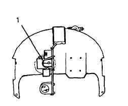
Attach the AH-1 sight (1) to the housing as
shown in Figure 4-34 with three pan-head
screws, lockwashers, and washers
(supplied).
NOTE
Before you install the AH-1 sight, you may have to
loosen the tensioning disc on the back of the sight.
This ensures proper alignment of the sight with the
mounting pattern of the visor housing.
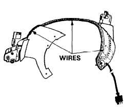
5. Referring to Figure 4-35, route the wires
(2) along the underside of the visor hous-
ing and secure them with electrical tape.
6. Insert the orange wire through the for-
ward hole and the violet wire through the
rear hole in the magnetic coupler mount-
ing area.
WARNING
Exercise care when using the soldering gun.
Figure 4-34. AH-1 Sight Installed
Figure 4-35. Routing Wires
7. QUALIFIED PERSONNEL ONLY: Using soldering gun (Item 12, Appendix B),
soldering flux (Item 13, Appendix E), and tin alloy solder (Item 18, Appendix E),
solder the two conductor wires to the magnetic coupler terminals as follows:
(a) Connect the orange wire to the terminal closest to the front of the visor
housing.
(b) Connect the violet wire to the terminal closest to the rear of the visor
housing.
NOTES
l When soldering the conductor wires, ensure that:
(a) the magnetic coupler is oriented with the solder terminals to
the right of the mounting area (over the feed-through holes).
(b) the conductor wires are long enough to be routed and installed
properly after they have been cut and stripped.
l Do not install the tapered block that you previously removed with the coupler;
this block will no longer be used.
4-37