TM 1-8415-216-12&P
CAUTION
Be careful not to cut the AH-1 cable when cutting through the glue
attaching the cable to the housing.
4. Cut through the glue attaching the cable (1) to the inside of the visor housing.
5. Pull the cable through the leg (2) of the visor housing.
WARNING
Exercise care when using the soldering gun.
6. Remove the screw and washer from the end of the sight assembly shaft (refer to
Figure 4-33). Pinch the locking spring holding the sight shaft and remove the
sight shaft from the sight assembly.
7. Remove the three screws and washers that attach the magnetic coupler to the
visor housing. Using soldering gun (Item 12, Appendix B), desolder the two
8
wires on the-magnetic coupler.
.
Pull the wires carefully through the holes in the front of the visor housing,
thereby removing the existing sight completely. Remove the three screws on the
sight assembly.
9. Remove the screw and spring washer attaching the tapered tensioning disk
from the back of the sight assembly, and attach the flat tensioning disk
(supplied). Remove V-2 mount from existing Cobra housing in accordance with
TM 9-1270-212-14&P.
Assembly
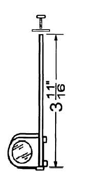
1. In order for the AH-1 sight to function properly
on the AIHS helmet, the sight shaft may have
to be modified by A QUALIFIED SUPPORT
UNIT. Measure the shaft length. If it is
3-11/16”, it has already been modified; proceed
to step 9. Otherwise, refer to Figure 4-33 and
perform steps (a) through (e) as follows:
(a) Clamp the rod in a bench vise.
(b) Use a metal-cutting hand saw (Item 16,
Appendix B) to cut the top end of the
shaft (the end from which the screw was
removed) so that the shaft measures
3-11/16” after cutting.
(c) Using a center punch, mark the center of
the shortened end.
(d) Use a #43 tap drill (Item 4, Appendix B)
to drill a hole to a depth of 5/16”.
(e) Using a #4-40 tap (Item 3, Appendix B),
thread the hole.
Figure 4-33. Modifying AH-1
Sight Assembly Shaft
4-36


