TM 1-8415-216-12&P
8. Referring to Figure 4-47, back the four thumbscrews (2) attaching the Cobra
visor housing to the helmet shell from the nut plates inside the helmet shell.
Remove the Cobra visor assembly (including visor housing, visor lenses, and
track assemblies) from helmet.
NOTE
A nut plate (8) on the underside of the helmet shell holds the posts in
place. If the post threads are stripped, remove lining, helmet, shock
(EAL) as directed in paragraph 4-13a, replace the nut plate, and rein-
stall the lining, helmet, shock (EAL).
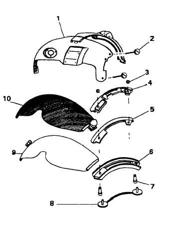
9. Unscrew the four thumbscrews (2) attaching the Cobra visor housing to the
visor assembly, and remove the housing (1) from tracks (4, 5, 6).
10. Disassemble visors (9, 10) and tracks by removing retaining rings (3) and
bushings (7). Repeat for other side.
11. Inspect disassembled components in accordance with Table 4-1. Replace
components as necessary.
12. Install the replacement Cobra visor assembly as follows:
(a) Place inner visor (9) over
lower track (6).
(b) Place middle track (4) over
inner visor (9). Insert bush-
ings (7) upward through
lower track (6) and middle
track (5) in that order.
(c) Place upper track (4) over
outer visor (10); place both
over middle track (5) and
bushings. Insert bushings
through upper track (4) and
reinstall retaining rings (3).
(d) Align housing (1) thumb-
screw holes over track
bushings, and install thumb-
screws (2) through housing
and bushings.
(e) Position housing and tracks
on helmet, aligning bush-
ings over posts from nut-
plate (8) protruding upward
through helmet (two on
each side); and start all
four thumbscrews.
(f) Tighten the four visor
assembly thumbscrews.
Figure 4-47. Cobra Dual Visor Module
4-44