TM 1-8415-216-12&P
d. Removing Standard Headset and Installing TEMPEST headset.
INITIAL SETUP
Personnel Required
Tools/Equipment
ALSE Specialist/Technician
or Personnel with ASI of
H2/Q2 (ALSE Qualified)
Screwdriver, flat-tip (GGG-S-121 TY1CL5DEB)
Gun-type electrical heater (803 1088)
Spatula (GGG-C-746)
Jeweler’s screwdriver set (CM3033)
Drill, electric (SP6039)
Bit, high-speed, (DBC19/64)
Materials/Parts
Microphone
(1680-ALSE-127-1)
Cable assembly (1680-ALSE-160-3)
OR
Cable assembly (1680-ALSE-162)
Cord assembly (94B8811)
NOTE
Before beginning this procedure, disengage the chinstrap
from the D-rings. This will ease the removal of the com-
ponents.
1. Loosen the adjustment for the strap assembly,
2. Detach the earcups from earcup retainer pads, and
pass them through the strap assembly, chin straps.
Allow the earcups to hang by the communications
cord.
NOTE
Keep the earcup assemblies for use during TEMPEST
installation.
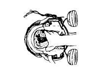
3. Referring to Figure 4-53, remove the lining, hel-
met, shock (TPL) from helmet by disengaging the
front and rear hook-and-pile fasteners.
4.
5.
6.
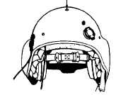
Referring to Figure 4-54, remove the screw, spring
washer, and post fastening the strap assembly, chin
to the center rear of the helmet shell. Retain the
screw, washer, and post for reassembly.
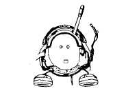
Referring to Figure 4-55, use a spatula (Item 2,
Appendix B) to separate the hook-and-pile fastener
attaching the lining, helmet, shock (EAL) to the helmet
shell.
Following the contour of the helmet shell, carefully
slide the lining, helmet, shock (EAL) out through the
back of the helmet.
Figure 4-53. Removing
Lining, Helmet, Shock
(TPL)
REAR RETENTION SCREW
Figure 4-54. Rear
Retention Screw
Figure 4-55. Removing
Lining, Helmet, Shock
(EAL)
4-49