TM 1-8415-216-12&P
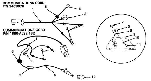
Installation of TEMPEST headset (refer to Figure 4-58)
1.
2.
3.
4.
5.
6.
7.
Ensure the microphone cord (4) is disconnected from the communication cord (1).
Insert the jack (5) with attached jack holder through the hole, and install the
grommet (6) into the hole in the shell. (If necessary, wet the grommet with plain
water to ease insertion.)
Slide the shrink tubing over the jack and the jack holder. Shrink the tubing with
the heat gun (Item 10, Appendix B).
Install two screws to attach the microphone connector with the jack holder plate
to the helmet.
If required, retie the strain relief plate (3) to the communications cord (1) in the
same manner in which the cord was originally tied.
NOTE
When properly tied, the knot (8) will be between the strain relief plate
and the helmet shell (9).
Attach the strain relief plate to the helmet shell with the screw (11), post (7),
and spring washer (10).
WARNING
Ensure that the HGU-56/P crushable earcups are used with the
TEMPEST headset.
NOTE
If installing communications cord P/N 1680-ALSE-162, enlarge the
hole in the left earcup using an electric drill (Item 9, Appendix B) and
a DBC19/64 drill bit (Item 8, Appendix B) before performing Step 7.
Insert the communications cord leads (2) from the outside of each earcup
(the original HGU-56/P earcup) through the holes.
Figure 4-58. TEMPEST Headset
4-51