TM 1-5855-265-20
3-55
3-12. PNVS TURRET ASSEMBLY INSTALLATION (cont)
CAUTION
Damage to guide pins, internal wiring, and
captive mounting screws can occur if captive
mounting screws are installed in PNVS turret
assembly NOT properly seated.
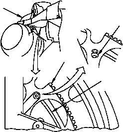
10. Check for correct installation of PNVS turret
assembly (2).
a. Check for rocking motion of PNVS turret
assembly by exerting light downward side-
to-side pressure. If rocking motion occurs,
repeat step 9 for proper seating.
b. Look up at underside of azimuth drive
gimbal assembly (1) and be sure guide pins
have not dropped into gear cutouts (step
9b).
c. If pins have dropped into gear cutouts,
repeat steps 9 and 10 for proper seating.
11. Move PNVS turret assembly (2) toward stow
(para 3-4) and find fifth captive mounting
screw (18).
12. Engage fifth captive mounting screw (18) in
threaded hole in baseplate (19) of PNVS
turret assembly (2).
NOTE
Do not overtighten captive mounting screws
when hand tightening. These screws will be
torqued to 30 in-lb after all screws have been
hand tightened.
13. Hand tighten screw (18).
2
18
1
19
310-014B