TM 1-5855-265-20
3-12
3-4. MOVING TADS TURRET ASSEMBLY MANUALLY (cont)
CAUTION
• Never rotate a turret without having electrical
power to release brake. Rotating a turret
against a locked brake will damage azimuth
drive gimbal assembly.
• Operating TADS/PNVS brake release switch
releases azimuth and elevation brakes.
Rotate turret assembly slowly. Rapid rotation
may cause turret assembly to bind in
azimuth and elevation.
NOTE
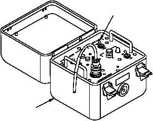
If brake release power supply assembly is not
connected, omit step 8 below.
8. Set MODE switch (6) on brake release power
supply assembly (7) to TADS position.
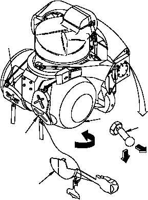
9. Move TADS turret assembly (9).
a. Pull TADS/PNVS brake release switch (8),
push down, and hold.
b. Turn TADS turret assembly (9) in direction
of arrow until TADS turret assembly stops.
c. Release TADS/PNVS brake release switch
(8). Check that TADS turret assembly
locks.
d. Install boresight protective cover (3),
dayside window cover assembly (4), and
nightside window cover assembly (5).
470-004A
6
7
5
4
3
PUSH
PULL
8
9
TURN
110-005A