TM 1-5855-265-20
3-7
3-3. MOVING PNVS TURRET ASSEMBLY MANUALLY (cont)
INTO STOW
CAUTION
Never rotate a turret without having electrical
power to release brake. Rotating a turret
against a locked brake will damage azimuth
drive gimbal assembly.
NOTE
If brake release power supply assembly is not
connected, perform step 6 below.
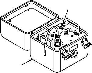
5. Set MODE switch (3) on brake release power
supply assembly (4) to PNVS position.
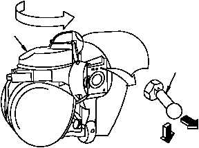
6. Move PNVS turret assembly (6).
a. Pull TADS/PNVS brake release switch (5),
push down and hold.
b. Turn PNVS turret assembly (6) in direction
of arrow until PNVS turret assembly stops.
c. Release TADS/PNVS brake release switch
(5). Check that PNVS turret assembly
locks.
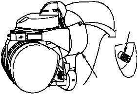
CAUTION
Improper tightening of two captive screws can
damage equipment. Do not overtighten captive
screws.
7. Close leftside fairing assembly (2) and tighten
two captive screws (1).
470-002A
3
4
PULL
PUSH
5
6
110-003A
TURN
110-004
2
1