TM 1-5855-265-20
3-80
3-16. PNVS SHROUD ASSEMBLY INSTALLATION (cont)
CAUTION
Use care when installing PNVS shroud
assembly so that you do not scratch the
coating on lens of elevation mirror assembly.
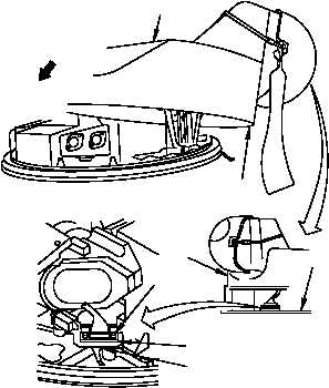
9. Gently lower PNVS shroud assembly (9) to a
point 6 inches above turret base (16).
a. Gently lower PNVS shroud assembly (9)
along a sloped path as shown by arrow.
b. Stop when rim (15) of PNVS shroud
assembly (9) at point (13) is no more than 6
inches above turret base (16).
CAUTION
Alternately turn each screwlock 1 to 2 turns. To
do otherwise will bend connector contacts.
NOTE
Step 10 requires two persons. One person
supports PNVS shroud assembly. The other
person connects PNVS shroud assembly
cable connector.
10. Connect PNVS shroud assembly cable
connector P1 (17).
a. Connect PNVS shroud assembly cable
connector P1 (17) to NSA connector J4
(18).
b. Tighten two screwlocks (19).
11. Have shroud assembly cable connector
installation inspected.
LOWER
VIEW ROTATED 180°
312-009B
9
15
13
19
17
18
16