TM 1-1510-218-10
3B-22
Signal reception is limited to line-of-sight and
power of the transmitting station with a maximum
range of 120 miles. The NAV receivers are protected
by 2-ampere circuit breakers placarded NAV #1; NAV
#2, located on the overhead circuit breaker panel,
Figure 2-16, Sheet 3.
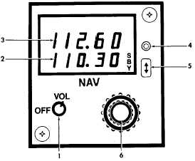
b. Controls and Functions.
(1) OFF / VOL Control. Turns the system
on/off, and adjusts audio volume.
(2) SBY Frequency Display. Provides a
digital readout of selected standby frequencies.
(3) Active Frequency Display. Provides a
digital readout of selected active frequencies.
(4) Light Sensor. Automatically adjusts
indicator display brightness.
(5) Frequency Transfer Switch. Allows
transferring of active or standby frequencies.
(6) Frequency Selector Knobs. Allows for
selection of desired frequency. Normally, frequencies
are selected while in the SBY display; however, to
bypass the frequency transfer mode of operation and
directly tune the set, pull out on the unit's small inner
concentric tuning knob until the standby display shows
dashes and select the desired frequency. To re-
engage the frequency transfer mode, push the small
tuning knob back in.
(7) PUSH TST / MODE Knob (#1 NAV/TAC).
Refer to Figure 3B-12. A self-test is provided to verify
range and bearing computation. When the NAV/TAC
control unit is tuned to a TACAN station, and the
PUSH TST / MODE knob is pressed, range data of 0
to 0.1 and bearing data of 180 ±2° will appear on the
DME slave indicator and both HSI's.
c. NAV Receiver Operation.
(1) Turn On Procedure. OFF / VOL switch –
Turn clockwise.
1. OFF/VOL Control Switch
2. SBY Frequency Display
3. Active Frequency Display
4. Light Sensor
5. Frequency Transfer Switch
6. Frequency Selector Knobs
7. PUSH TST Mode Knob
Figure 3B-12. #1 NAV/TAC Control Unit
1. OFF / VOL Control Switch
2. SBY Frequency Display
3. Active Frequency Display
4. Light Sensor
5. Frequency Transfer Switch
6. Frequency Selector Knobs
Figure 3B-13. #2 NAV Control Unit


