TM 1-1510-218-10
3B-20
(9) Inclinometer.
Gives
the
pilot
a
conventional display of aircraft slip or skid, and is used
as an aid to coordinated maneuvers.
(10) Attitude (ATT) Test Switch. Operates the
attitude self-test. When pressed, the sphere will show
approximately a 20° right bank and a 10° pitch-up
attitude, and the ATT warning flag will appear.
(11) Glideslope Scale and Pointer. Displays
aircraft deviation from glideslope beam center only
when tuned to an ILS frequency and a valid glideslope
signal is present. The aircraft is below glide path if
pointer is displaced upward. The glideslope dot
represents approximately 0.4° deviation from the
beam centerline.
(12) GA Annunciator. Illuminates when go-
around mode has been selected.
3B-17. TURN AND SLIP INDICATORS.
For information on turn and slip indicators, refer
to Chapter 2, Paragraph 2-90.
3B-18. RADIO ALTIMETER INDICATOR.
a. Description. The AA-300 Radio Altimeter
Indicator provides the pilot with actual altitude of the
aircraft.
The
indicator
displays
radio
altitude
information from 2500 feet to touchdown, with an
expanded scale under 500 feet.
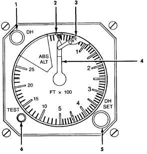
b. Controls and Functions. Refer to Figure
3B-10.
(1) Decision Height (DH) Annunciator. The
DH annunciator will illuminate when the aircraft is at or
below the selected decision height.
(2) Decision Height Bug. The decision
height bug is set to the desired decision height, by the
DH SET knob.
(3) Failure Warning Flag. The OFF warning
flag will be in view whenever the system information is
unreliable.
(4) Altitude Pointer. The altitude pointer will
point to the existing altitude.
(5) DH SET Knob. The DH SET knob is
used to set the decision height bug to the desired DH.
1. DH Annunciator
2. Decision Height Bug
3. Failure Warning Flag
4. Altitude Pointer
5. DH SET Knob
6. TEST Push Button
Figure 3B-10. Radio Altimeter Indicator
(6) TEST Push Button. When pressed, the
OFF warning flag will come in to view and the altitude
pointer will indicate approximately 100 feet. Release
of the button will cause the altitude pointer to return to
existing altitude, and OFF warning flag to retract.
3B-19. ALTITUDE SELECT CONTROLLER.
a. Description. The altitude select controller
provides a means for setting the desired altitude
reference for the altitude alerting and altitude preselect
system. It is protected through a 1-ampere circuit
breaker, placarded ALT ALERT, located on the
overhead circuit breaker panel, Figure 2-16, Sheet 3.
b. Controls and Functions. Refer to Figure
3B-11.
(1) Altitude Display. Displays the selected
altitude.
(2) Selector SET Knob. The selector SET
knob is used to set the desired altitude.