TM 1-1510-218-10
3B-23
(2) Receiver Operating Procedure.
1. Frequency selector – Select desired
frequency and press the frequency
transfer switch.
2. NAV 1 or 2 switch (Figure 3B -1) – As
required.
3. VOL control – As required.
(3) Shutdown Procedure. OFF / VOL control
– OFF.
3B-22. ADF RADIO SETS (KDF-806).
a. Description. Two ADF radio sets are
installed. Refer to Figure 3B -14. The units are
airborne low frequency radio direction finders that
receive signals from transmitters in the 190 to
1750 kHz range to provide a visual and aural
indication of the aircraft's bearing in relation to the
transmitter. The set can also be used for homing and
position fixing. The KDF-806 has a Beat Frequency
Oscillator (BFO) function, used to more accurately
tune weak signals. Reception distance of reliable
signals depends on the power output of the
transmitting station and the atmospheric conditions.
Bearing indications are displayed visually on the RMI's
and aural signals are applied to the audio control
panels. The system is protected by two 2-ampere
circuit breakers, placarded ADF 1 and ADF 2, located
on the overhead circuit breaker panel, Figure 2-16,
Sheet 3.
The KDF-806 incorporates a KFS-586A control
unit. The control unit contains a digital display that
presents both the active and standby frequencies. A
photocell automatically adjusts the display brightness
according to changes in ambient light conditions. The
KFS-586A switches/controls provide power to the
receiver, control the audio output level, control the
OFF BFO ADF, and ANT BFO modes of the receiver,
maintain the active and standby frequencies, and tune
the receiver to the active frequency. The KFS-586A
will retain the active and standby frequencies through
a power off condition.
b. Controls and Functions.
(1) Control Display. Provides a display of
selected frequencies and bearing validity. The display
contains two frequencies and an X character. The
upper frequency is the active frequency, or the
frequency to which the receiver is tuned. The lower
frequency is the standby frequency. The standby
frequency is changed by the frequency select knobs in
the lower right corner of the control unit. An X to the
right of the active frequency informs the pilot that the
bearing indicator (RMI) directional information is not
valid.
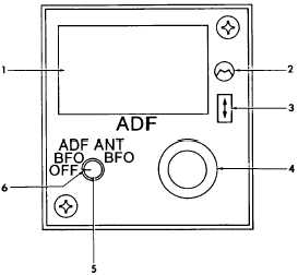
1. Control Display
2. Light Sensor
3. Frequency Transfer Switch
4. Frequency Select Knobs
5. Volume Control Knob
6. OFF / ADF BFO / ANT BFO
Function Control Knob
Figure 3B-14. ADF Control Unit
(2) Light Sensor. A photocell automatically
adjusts the display brightness according to changes in
ambient light conditions.
(3) Frequency Transfer Switch. Provides a
means of interchanging the active/standby displayed
frequencies. The transfer switch, when momentarily
pressed, causes the active and standby frequencies to
interchange. When the transfer switch is pressed and
held, the two frequencies interchange on the display
and approximately 2 seconds later the standby
frequency will blank out. Pressing the transfer switch
momentarily again will cause the standby frequency to
reappear.
(4) Frequency Select Knobs. Provides a
means of selecting frequencies. The normal method
of selecting a frequency is with both the active and
standby frequencies showing. The frequency select
knobs will then tune the standby frequency; however,
the active frequency may be changed by pressing and
holding the frequency transfer switch for approximately
2 seconds. The standby frequency display will blank
out. The active frequency display may then be directly
tuned by rotating the frequency select knobs.


