Note:
(7) Install spray boom assemblies to tank
installation, using figure 4-2 and the following steps as
Front boom cable passes under pump
guides:
support strut on tank installation (29).
(a) Remove cap (30) from end threads of
1. Insert wire-rope shackle (5) through loop
boom tube.
in end of cable assembly.
(b) Remove plug (31) from end of center
2. Secure wire-rope shackle to holes in
section boom on tank installation (29).
end of lower channel rail of tank installation (29) with
(c) Lightly lubricate threads on connector of
screw (4), washer (3), and nut (2).
(h Make sure rear boom cables have slack.
spray boom tube with suitable thread lubricate.
(d) Attach boom tube to center section boom
Tighten turnbuckle on inboard forward cable until tip
with nozzles aft. Tighten boom attaching nut handtight
of boom is about 3 inches forward of boom centerline.
only at this time.
Then tighten turnbuckle on inboard rear cable to
(e) Attach boom support strut (15), with rivet
adjust boom back to centerline position.
(i) Repeat the process of step (h) preceding
heads up, to inboard tube clamp of spray boom
for outboard cables, except reduce boom deflection for
assembly (19).
Secure with clevis bolt (14), washer
this step to 2 inches.
(13), and nut (12). Attach other end of strut to lower hole
(j) Firmly tighten boom tube to boom center
in end bracket located at upper end of tank installation
(29). Secure with screw (11), washer (10), and nut (9).
section. Hold boom tube securely with strap wrench,
(f) Attach upper boom cable of spray boom
while tightening boom attaching nut.
(k) Check to see if boom tubes are straight.
assembly (19) to upper hole in tank end bracket of tank
installation (29). Secure with screw (8), washer (7), and
If not, repeat preceding steps as required.
(l) Upon completion of cable adjustment, if
nut (6).
(g) Attach front and rear boom cables of
available, use MS 21256 lock clips to secure turnbuckles
spray boom assembly (19) to tank installation as follows:
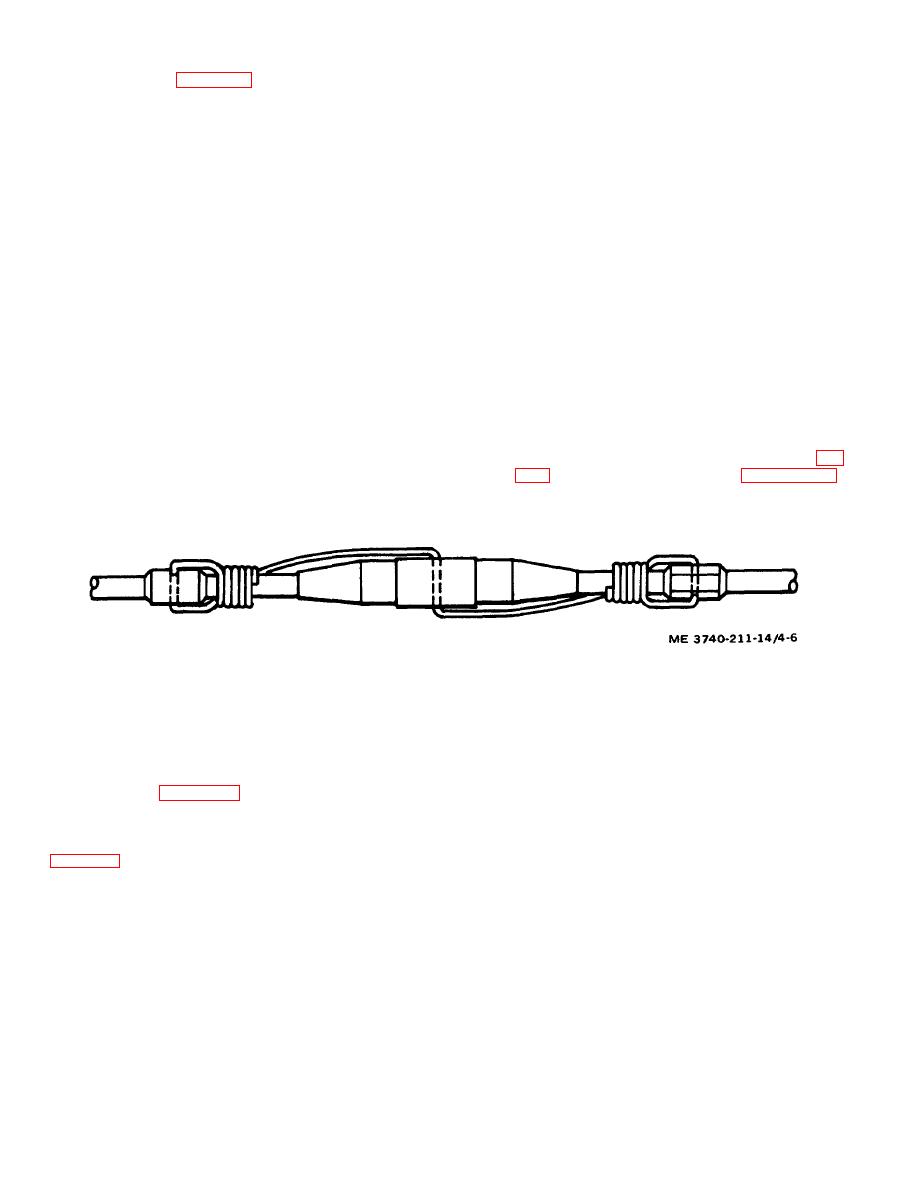
or 0. 041-inch diameter stainless steel lockwire (1, fig.
Attach lockwire per figure 4-6, in
accordance with MS 33540.
Figure 4-6. Turnbuckle safetying diagram.
(2) Remove spray boom assemblies as follows:
4-4. Removal from Helicopter
(a) Support spray boom assembly (19) to
a. Usage of the insecticide sprayer is such that it
prevent damage.
normally is removed from the helicopter immediately
(b) Remove lockwire (1) or clips from all
after use. Removal consists of thoroughly flushing and
turnbuckles. Loosen turnbuckles as needed to provide
cleaning the system, as well as removal from the
cable slack.
helicopter. Use figure 4-2 and the following steps as
Note:
guides:
Retain all attaching hardware by replacing in
(1) Thoroughly drain and clean the tank and all
attachment points from which removed.
fluid lines as described in the post flight operation (ref
(c) Remove nuts (2), washers (3), and
screws (4), retaining wire-rope shackles (5) to tank
Use noncorrosive mineral oil following use of oil-
installation (29). Remove wire-rope shackles from front
base spray fluid. Use water following use of water-
and rear boom cable assemblies of spray boom
base spray fluid. Use the liquid loading system for this
assembly (19).
operation to clean that system at the same time.
4-10


