TM 1-5855-265-20
3-63
3-12. PNVS TURRET ASSEMBLY INSTALLATION (cont)
NOTE
Check measurements made in step 29. Make
necessary adjustments before installing seal
access cover.
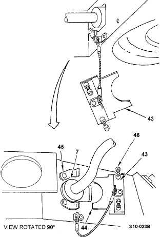
33. Install seal access cover (43).
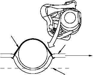
a. Put cutout portion of seal access cover (43)
near rubber seal (7). Make sure two tabs
(44) line up with two clips (45).
b. Push seal access cover (43) against seal
(7) while sliding tabs (44) under clips (45).
Stop pushing when the two captive screws
(46) engage mounting holes.
c. Tighten captive screws (46).
NOTE
If W10 harness does not have EMI/RFI
shielding modification, install second tiedown
strap around loop in cable near rubber seal,
see para 3-11, step 1).
34. Install tiedown strap (47).
NOTE
• After the PNVS W10 harness is installed
and secured, slew the TADS turret gimbal
assembly in azimuth to ensure that
approximately 1/2 of an inch or greater
clearance is between the W10 cable and
the wire strike fairing.
• The PNVS turret may also be slewed in
azimuth to ensure the W10 is secured
properly and does not push out from the
access hole.
• Slewing should be done manually by
applying aircraft power and utilizing the
brake release switch on the AIA.
35. Have PNVS turret assembly installation
inspected.
36. Perform followup.
END OF TASK
310-058C
P1
CONNECTOR
W10
BOTTOM OF
AIR DUCT
NOTE:
BOTTOM OF W10 CABLE AT TIE POINTS
SHOULD BE ABOVE BOTTOM OF AIR DUCT.
AIR
DUCT
47