
TM 55-6610-247-40
body assembly (47), and secure it with screw (52).
CAUTION
Replace balance assembly (45) in mechanism body and
After tension has been applied to
secure balance assembly with screw (51).
hairspring and wheel pinion engaged
e. Replace setting assembly 140 and secure with
with sector, the sector must be held
screw (51).
at all times until rocking shaft
CAUTION
assembly is connected to diaphragm
Insure
none
of
hairspring
assembly with link. If this is not
convolutions is between mechanism
done,
hairspring
tension
will
body and bridge plate when securing
disengage pinion from sector and
bridge plate to mechanism.
cause damage to hairspring.
f.
Insert wheel and hairspring assembly (33),
m. Hold rocking shaft in this position be pressing
hairspring up, through cutout in mechanism body, and
against counterweight. and with a tooth pick turn wheel
place pivot into setting assembly (40). Hold bridge
counterclockwise six revolutions (24 spokes) to apply
assembly (30) over mechanism and insert hairspring into
tension to hairspring. With this tension maintained on
post. Secure it with a new tapered pin (29) and cut off
hairspring, slowly reengage sector with %wheel pinion.
excess. Hairspring should be adjusted so first leaf is
n. With tweezers, hold diaphragm link in line with
parallel to bridge plate. Secure bridge assembly to
slot in calibration arm of rocking shaft and slowly mole
mechanism with screws (28)
sector by its counterweight until bearing hole in link and
g. Adjust end play of wheel and hairspring assembly
bearing hole in calibration arm are aligned. Insert new
(33) to 0.002 inch by moving setting assembly (40) in
bearing pin in aligned holes.
mechanism body. Hairspring should be evenly spaced
o. With small pair of needle-nose pliers. press head
between hairspring disk and surface of top plate, and all
of pin until it bites into calibration arm. Bend pin at arm
convolutions should lie in same plane. Approximately
and toward rocking shaft. Test freedom of link. Link
three or four coils of spring should extend past disk
should haze no plan on bearing pin but should not bind in
opposite hairspring post.
calibration arm.
h. Check freedom of movement of wheel and
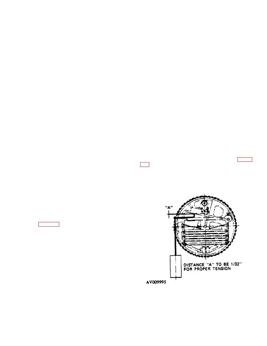
p. A special balance weight, part no. TE630A.1 is
hairspring assembly.
Place mechanism body,
necessary to adjust balance arm tension properly Figure
diaphragm up, on assemble, stand. With hairspring
relaxed, rotate wheel one-fourth turn and allows it to
noted that reference A shows a clearance of 1 32 inch
swing free. 'Wheel should return to its original position
between weight and mechanism body when weight is
within 1/8 inch.
suspended on balance arm. To correct any error in
CAUTION'
tension of balance arm, turn balance assembly post and
When inserting rocking shaft, do not
secure balance screws (51).
damage teeth of sector or wheel
assembly.
i. Insert rocking shaft assembly (20) through cutout
of mechanism body.
j. Adjust rocking shaft assembly by repositioning
setscrew (19 figure 2-2) until an end play of 0.003 inch is
obtained.
CAUTION
When checking tracking of sector,
care shall be exercised not to allow
wheel to run out of mesh while
tension is applied to hairspring, as
this will cause wheel to rotate rapidly
and damage hairspring.
k. Sector should track approximately in center of
wheel pinion of wheel and hairspring assembly (33) and
in one plane. Lift up or press down on spokes of sector
until correct alignment is obtained.
Figure 2-6. Application of Balance Weights.
l. With mechanism on assembly stand. diaphragm
up, turn rocking shaft in a clockwise direction until sector
is disengaged from wheel pinion, and allow wheel to
come to rest with no tension on hairspring.
2-9
