
TM 55-6610-247-40
f. Calibration arms should not be removed from
corrosion and their polished surfaces must have a
mirror-like finish.
rocking shaft unless they are damaged.
d. Hairspring must be of proper length and in good
g. Place rocking shaft assembly (20. figure 2-2).
condition.
jewel end up. in a clamp and hold clamp in a vise. With
e. Bearing holes in links must not be worn.
a scribe or other sharp pointed tool. break up jewel (23)
f. Both compensating pins of aneroid diaphragm
and remove all fragments. With a no. 53 drill head in a
pin vise. drill through jewel setting. Using a 1-72 tap.
must rotate from very light finger pressure.
grind end flat. Holding tap in a pin vise. screw it one or
two turns into jewel setting. Pull tap and setting out of
2-4. Repair and Replacement.
shaft. Place a new jewel setting assembly on shaft so flat
Repair and replace as follows:
face is up and tap it into place with a suitable punch.
a. To remove a jewel from an assembly, support
h. Chuck shoulder of pivot (22) in a jeweler's lathe
unit in a suitable manner and tap it out. Replace jewel by
and carefully pull assembly away from pivot with a slight
tapping it into place from opposite side.
twisting motion. To replace pivot, place rocking shaft in
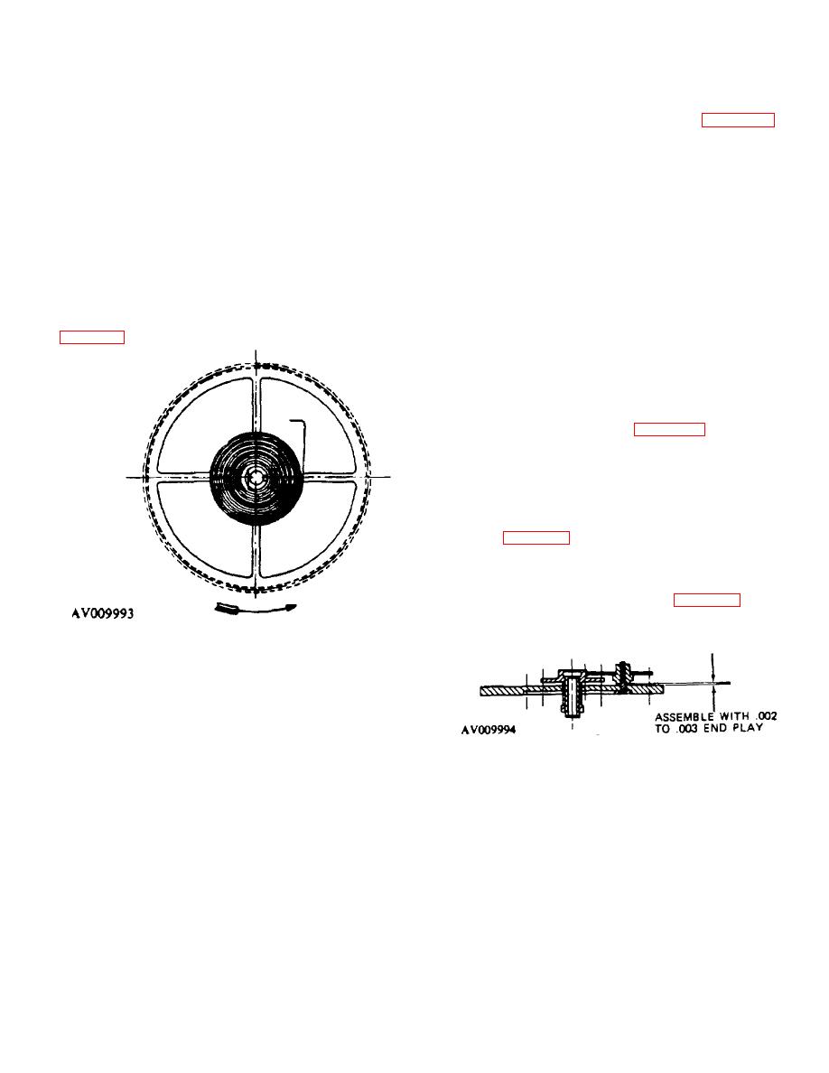
b. With a pin vise, hold wheel in a vertical plane and
clamp (as shown above for replacement of jewel), and
check position of hairspring. Wheel hairspring should be
hold clamp in a vise. Tap new pivot into place using a
parallel to disk, and coils should lie in same plane. Refer
suitable punch.
to figure 2-4.
NOTE
If pivot is loose, squeeze end of shaft in
collet of a jeweler's lathe to make hole
smaller before pressing in pivot.
i. Place plate assembly (4. figure 2-2) on staking
frame with hand staff in suitable hole and wheel up. With
suitable punch, tap short hand staff (7) free of wheel
assembly (8) Place hand staff in suitable hole in staking
frame so its shoulder rests on table. Locate plate and
bushing assembly (9) on hand staff, then place wheel
assembly (8) fin staff and tap it in place with suitable
punch. See figure 2-5, for arrangement of parts.
Figure 2-5. Bearing Plate.
j. While holding plate assembly (4. figure 2-2). press
staff of pinion (5) with back end of tweezers until it is
flush with intermediate ;-heel and hub assembly (6).
Figure 2-4. Position of Wheel Hairspring.
CAUTION
If hairspring is mounted on wheel, do
not spin wheel at high speed, this will
destroy hairspring.
c. Check concentricity of wheel in a truing caliper.
Any eccentricity will be apparent by comparison with a
Figure 2-5. Bearing Plate
fixed guide. Concentricity may also be checked by
spinning wheel in a jeweler's lathe and checking its
Place pointed ends of tweezers between bearing plate
periphery against a guide.
and wheel, and pry off wheel and hub assembly.
d. Hold wheel assembly in a pin vise. Place a
jeweler's screwdriver between disk and hairspring collet
CAUTION
and pry hairspring from staff.
Before replacing
Use care when prying off wheel
hairspring, collet must be squeezed together to insure a
assembly so as not to bend staff of
tight fit.
pinion.
e. To remove wheel pinion. support it on a suitable
staking frame and tap it out.
k. Insert staff of pinion (5) in bearing hole from front
side of plate. While holding pinion in place with finger,
place intermediate wheel and hub
2-7
