
TM 55-6610-247-40
s. Loosen screw 150) and remove jewel setting
modified to a 'D' configuration pointers (16, 17, and 18).
ring (20) and dial (23) shall be discarded
assembly 140).
f. Remove gear assemblies (29, 30 and 31).
NOTE
g. Remove pin (32) and retaining ring (33).
The arm and balance assembly (41)and
h. Before removing top plate mechanism assembly
diaphragm assembly (46) should not be
(34). remove shoulder screws, (3, figure 2-2). Lift off top
removed from mechanism body unless
bearing plate assembly (4) and wheel assembly (10).
they are to be replaced.
i. 'With a pair of parallel jaw pliers, grasp a spoke of
t. Loosen screw (51) and remove arm ,and balance
top plate mechanism assembly (34, figure 2-1) and
assembly (41).
remove it from case (47). Refer to paragraph 2-4 for
u. Loosen screw (52) and remove diaphragm
repair and
replacement procedures of top plate
assembly (46) from body assembly (47).
mechanism assembly (34).
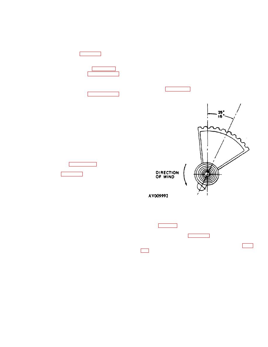
v. Rocking shaft and sector assembly has a strong
j. Grasp a spoke of mechanism assembly (36) and
hairspring. Figure 2-3 shows direction of wind and
remove it from case (47). Refer to paragraph 2-4 for
position of end of hairspring so it will have three-fourths
repair and
replacement procedures for mechanism
to one-turn tension when pinned at assembly.
assemblv (36).
j.l. If installed, remove shim (36A) from the case.
k. Place top plate mechanism assembly (1, figure 2-
21, diaphragm down, in a suitable assembly stand.
CAUTION
Pressure shall be applied evenly as any
side pressure may break hand staff
pinion
I. With back end of a pair of tweezers, press down
on hand staff pinion (14), pressing jewel setting
assembly (13) from mechanism body.
m.
Lift pinion (35, figure 2-11 off top plate
mechanism assembly (34).
n. Remove pin (15, figure 2-2), diaphragm link 16 h,
and calibration arm (17).
o.
Remove pin (42), balance link (44), and
calibration arm 143).
NOTE
Calibration arms II - and 43) should be
left in shaft assembly 120). Move these
Figure 2-3. Direction of Hairspring on Rocking
arms for adjustment and balancing only.
Shaft.
2-2. Cleaning.
p. Remote setscrew (191, then lift shaft assembly
Clean all parts by washing them in clean benzene,
1201 straight up so lower pivot clears jewel. and remove
(item 2, table 1-3), and dry with clean, dry. compressed
it from mechanism through cutout provided in front of
air. Clean pivots by pressing them into end grain of dry
casting.
pithwood (item I 11. table 1-3) and twirling them
q. Remove screws 128) and carefully pry bridge
between fingers. Clean jewels and bearing holes by
assembly 130) from mechanism body. Carefully turn
twirling sharpened end of a pegwood stick (item 12, table
bridge assembly over toward center of mechanism
assembly 1121. Holding bridge assembly firmly at right
with a no. 2 watchmaker's brush dipped in benzene.
angles to mechanism, push tapered pin 42') free with
2-3. Inspection.
pliers.
Inspect as follows:
r. With tweezers inserted through opening in side -if
a. Inspect all gear teeth for wear or damage.
casting. grip pinion of wheel and hair- spring assemble,
b. Inspect jewels for chips or cracks.
(33) and lift it straight up so lower pivot clears jewel (31).
c. All pinions and pivots must be free from
Move wheel and hairspring assembly (33) along channel
in mechanism body and out.
Change 5 2-6
