TM 1-1510-225-10
2-113
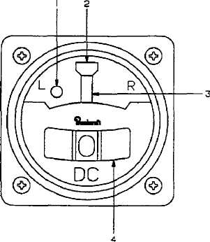
1. Gyro Warning Indicator
2. Rate Of Turn Index
3. Rate Of Turn Indicator Needle
4. Inclinometer
Figure 2-34. Turn and Slip Indicator
c. Description F3 . Two turn and slip indicators
are installed separately on the pilot and copilot sides of
the
instrument
panel.
These
indicators
are
gyroscopically operated by dc power and are protected
by a circuit breaker placarded PILOT TURN & SLIP on
the right side circuit breaker panel. The copilot’s
indicator is a vacuum instrument operated by engine
bleed air pressure that is reduced to approximately 2.0
inches Hg. by an inline orifice.
d. Turn
and
Slip
Indicator
Controls,
Indicators, and Functions.
(1) Gyro Warning Indicator. Presence
indicates loss of electrical power to instrument.
(2) Rate of Turn Index. Used in conjunction
with the rate of turn indicator needle to show direction
and rate of turn.
(3) Rate of Turn Indicator Needle. Deflection
left or right indicates direction and rate of turn.
(4) Inclinometer.
Deflection
of
the
inclinometer ball from the center of the inclinometer
tube indicates that the aircraft is in a slipping or
skidding turn, depending on turn direction.
2-78. AIRSPEED INDICATORS.
a. Indicated Airspeed. Two identical airspeed
indicators are installed separately on the pilot's and
copilot's sides of the instrument panel. These
indicators require no electrical power for operation.
The indicator dials are calibrated in knots from 40 to
300. An aneroid operated striped pointer automatically
displays the maximum allowable airspeed at a given
aircraft altitude.
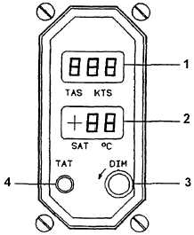
b. TAS/TAT Indicator. An electrically heated
probe located aft of the nose wheel well sends
airspeed and temperature inputs to the air data
computer. The computer generates this information
into Airspeed and Air Temperature data that is
displayed on the TAS / TAT instrument located on the
copilot's side of the instrument panel. Icing of the
probe is prevented (when airborne), by placing the
switch placarded PROBE HEAT / OFF to the PROBE
HEAT (On) position. The probe heater is wired
through a squat switch on the right main landing gear,
which disables probe heat while the aircraft is on the
ground, regardless of the PROBE HEAT switch
position. Probe heat should be used when the other
aircraft anti-icing / deicing systems are activated. The
combined Total Airspeed, Static Air Temperature /
Total Air Temperature indicator, Figure 2-35, provides
a digital display of both TAS and SAT or TAT as
generated by the air data computer. Table 2-10 for
clarification and explanation of controls and functions.
1. True Airspeed Indicator
2. Static/True Air Temperature Indicator
3. Front Panel Dimming Control
4. True Air Temperature Push Button
Figure 2-35. Airspeed Indicator


