TM 1-1510-225-10
2-116
2-81. STANDBY ATTITUDE INDICATOR.
a. Description R. An electrically operated
standby attitude indicator, Figure 2-38, with a backup
battery system, is located on the pilot's instrument
panel, Figure 2-17. The backup battery is located on
the bottom shelf on the copilot's side of the nose
compartment, and is charged from the aircraft NO. 3
AVIONICS BUS. Backup battery protection is
provided by a 15-ampere circuit breaker, placarded
STBY BAT, and the standby attitude indicator is
protected by a 2-ampere circuit breaker placarded
HORIZON IND. Both circuit breakers are located on
the right sidewall circuit breaker panel Figure 2-6,
Sheet 1 of 5. The standby attitude indicator is capable
of providing accurate attitude indications for up to
30 minutes with the backup battery following a total
aircraft electrical system failure.
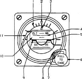
1. Bank Angle Scale
2. Bank Angle Index
3. Bank Angle Pointer
4. Pitch Angle Scale
5. Horizon Line
6. Caging and Pitch Trim Knob
7. Pitch Trim Pointer
8. Pitch Trim Scale
9. Miniature Symbolic Aircraft
10. Drum
11. Power Warning Flag
Figure 2-38. Standby Attitude Indicator R
b. Description T3. The standby attitude
indicator, Figure 2-39, located under the TCAS display
on the pilot’s instrument panel, is powered by engine
bleed air, and provides a visual reference of the
aircraft pitch and roll. The attitude indicator is
comprised of a self contained gyro to erect the sphere
which provides the pitch and roll reference, an
indicating symbol which represents the aircraft, and a
horizontal line behind the indicating symbol which
represents the horizon. The moveable indicating
symbol may be adjusted vertically to correct for
variations in level flight attitudes by a small knob
located on the front base of the indicator. Table 2-11
describes the functions of the controls/indicators.
1. Attitude Sphere
2. Roll Index
3. Roll Pointer
4. Horizon Line
5. Pitch Knob
6. Pitch Scale
7. Symbolic Miniature Aircraft
Figure 2-39. Standby Attitude Reference Indicator
T3