TM 1-1510-225-10
2-112
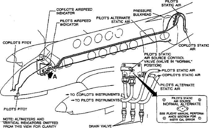
Figure 2-33. Pitot and Static System
2-76. STATIC AIR SYSTEM.
a. Description. The static system, Figure 2-33,
provides static air pressure for the pilot's and copilot's
airspeed
indicators,
copilot's
altimeter
air
data
computer, and pilot's and copilot's vertical speed
indicators. The static air pressure ports are located on
the right and left sides of the aft fuselage exterior skin.
b. Alternate Static Air Source. An alternate
static airline, which terminates just aft of the rear
pressure bulkhead, provides a source of static air for
the pilot's instruments in the event of source failure
from the pilot's static airline. A control on the right
cockpit sidewall, placarded PILOT'S STATIC AIR
SOURCE, may be actuated to select either the
NORMAL or ALTERNATE air source by a two-
position selector valve. The valve is secured in the
NORMAL position by a spring clip.
2-77. TURN AND SLIP INDICATOR.
a. Description R . The pilot and copilot are
each provided with a turn-and-slip indicator as
illustrated in Figure 2-34. The turn needles on these
instruments indicate the direction and rate of turn. A
one needle width deflection indicates a two-minute
(180 per minute) turn. Deflection of the inclinometer
ball from the center of the inclinometer tube indicates
that the aircraft is not in a coordinated turn (that it is
either in a slipping or skidding turn, depending on
direction of turn). These indicators are gyroscopically
operated
and
electrically
powered
through
two
individual 5-ampere circuit breakers placarded PILOT
TURN & SLIP, and COPLT TURN & SLIP, located on
the right sidewall circuit breaker panel.
b. Description T3 . One turn and slip indicator
is installed on the pilot side of the instrument panel.
The indicator is gyroscopically operated. The unit is
operated by dc power and is protected by a circuit
breaker, placarded PILOT TURN & SLIP, on the right
side circuit breaker panel.


