TM 1-1510-225-10
2-118
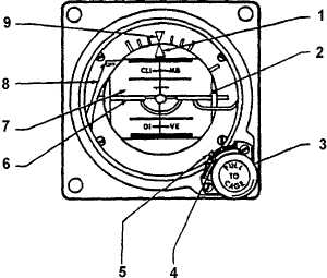
1. Roll Pointer
2. Horizon Line
3. Caging / Pitch Trim Knob
4. Trim Pointer
5. Pitch Trim Scale
6. Miniature Aircraft
7. Drum
8. Power Warning Flag
9. Roll Index
Figure 2-40. Standby Attitude Indicator F3 OSA
Table 2-12. Standby Attitude Indicator Control / Functions F3 OSA
NO.
FUNCTION
1
Indicates vertical in any roll attitude.
2
Indicates earth's horizon relative to aircraft pitch attitude.
3
Pulled to cage the indicator and rotated to adjust the miniature aircraft attitude.
4
Pointer indicates trim displacement.
5
Measures displacement of miniature aircraft.
6
Represents aircraft nose and wings. Indicates roll and pitch attitude relative to the horizon. Adjustable
through pitch knob for varying pitch attitudes.
7
Directly linked to the spin motor to provide direct reading of aircraft movement in roll and pitch. Marked
each 5° in pitch. Black area of drum indicates dive; blue or gray area indicates climb.
8
In view, indicates power off, caged condition, open motor winding, or loss of power. Retracted, normal
operation.
9
Rotates with aircraft to provide measurement of angular displacement by the roll pointer during
maneuvers.
(7) Pitch Trim Pointer. Indicates amount of
vertical trim displacement applied to the miniature
aircraft.
(8) Pitch Trim Scale. Provides a means of
measuring the amount of vertical trim displacement
applied to the miniature aircraft.
(9) Miniature
Symbolic
Aircraft.
The
relationship between the fixed miniature aircraft
symbol and the movable attitude sphere display
aircraft pitch and roll attitudes.
(10) Drum. The drum is directly linked to the
gyro to provide a direct measurement of aircraft
movement around the pitch and roll axis.
(11) Power Warning Flag. Presence of the
power warning flag indicates no power to the unit, a
caged condition, or open gyro motor winding.
e. Standby Attitude Indicator Backup Battery
Power System Controls, Indicators, and Functions.
R The controls and indicators for the standby attitude
indicator backup battery power system are located on
the audio control panel. Refer to Figure 3A-1.


