TM 55-4920-227-15
connected to a shaft that actuates the control nut and
speed to a minimum, stop the unit and
pivoted strut, which slides the movable varidisc on the
disconnect the power source.
main motor shaft toward its companion disc thus causing
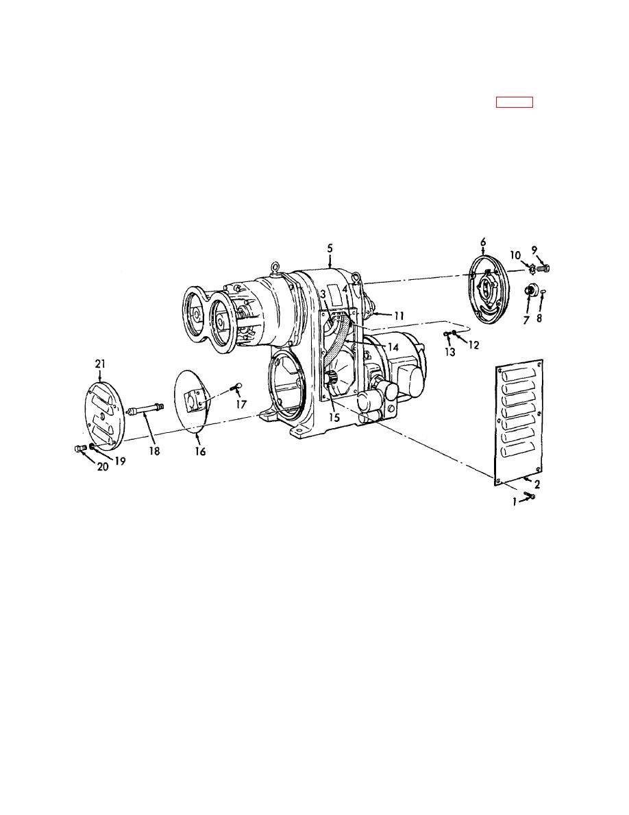
(2) Remove six screws (1, fig. 16) and remove
the varibelt to climb upward on the tapered vaidiscs to a
the louvered cover (2) from each side of the
larger diameter. Simultaneously, the varibelt causes the
case frame (5).
movable varidisc on the driven shaft to retract, permitting
(3) Remove four screws (20) and lockwashers
the varibelt to assume a smaller diameter increasing the
(19) from the end cover (21) and remove the
driven shaft speed, while the main motor speed remains
end cover from the case frame.
constant.
(4) Remove the lubrication extension (18) from
the end of the motor shaft (15).
54. Varibelt Removal and Installation
a. Removal,
(1) Start the test stand and reduce the varidrive
1
Screw (12 rqr)
12
Washer
2
Louvered cover (2 rqr)
13
Screw (3 rqr)
3
Varidisc (Movable)
14
Varibelt
4
Varidisc (Stationary)
15
Motor shaft
5
Case frame
16
Varidisc (Stationary)
6
End cover
17
Screw, cap, hex -hd, 1/2-13 x 2 1/4 in. (4 rqr)
7
Busing retainer nut
18
Lubrication extension
8
Screw (2 rqr)
19
Washer
9
Screw (4 rqr)
20
Screw (4 rqr)
10
Washer (4 rqr)
21
End cover
11
Bearing cap
Figure 16. Varibelt removal and installation.
AGO 6729A
28


