
TM 55-4920-227-15
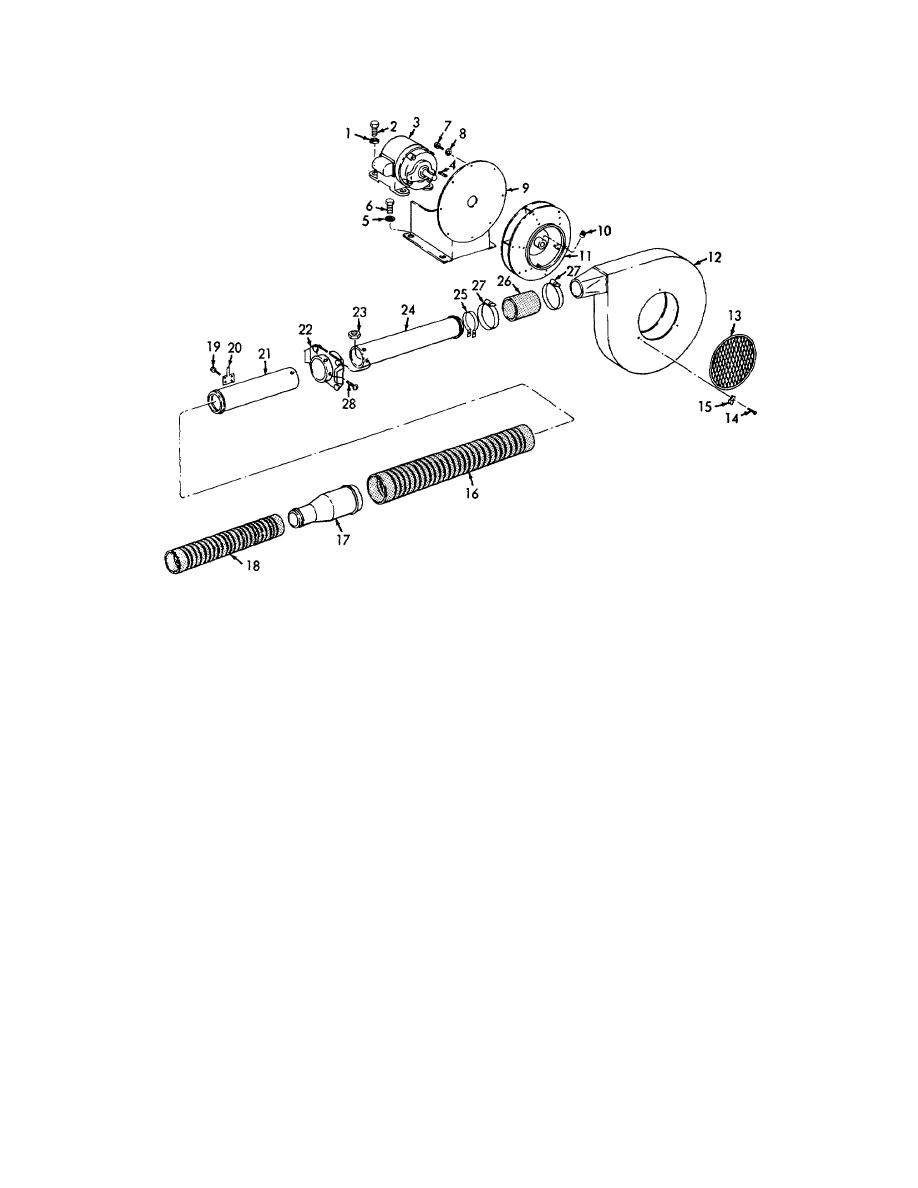
1
Washer, flat, 3/8 in. (4 rqr)
16 Air hose, flexible rubber, 3 in. I.D. x 36 in. lg
2
Screw, cap, hex-hd, 3/8-16 x 1 1/2 in. (4 rqr)
w/1 in. soft ends
3
Motor
17 Hose reduce, 3 in. to 2 in.
4
Machine key
18 Air hose, flexible rubber, 2 in. I.D. x 36 in. lg
5
Washer, flat, 3/8 in (4 rqr)
w/1 in. soft ends
6
Screw, cap, hex-hd, 3/8-16 x 1 3/4 in. (4 rqr)
19 Screw, thread forming No. 7 x 3/8 in. (4 rqr)
7
Screw, cap hex-hd, 3/8-16 x 1 in. (8 rqr)
20 Pitot tube
8
Washer, flat 3/8 in.
21 Tube
9
Motor support
22 Valve, 3 in round blast gate
10
Screw (2 rqr)
23 Nut, plain, hex. No. 10-32 (6 rqr)
11
Fan
24 Tube
12
Blower housing
25 Tube mounting damp
13
Screen
26 Hose, radiator. 3 in. I.D. x 3 in. lg
14
Screw, thread forming, No 7 x 3/8 in. (3 rqr)
27 Hose clamp (2 rqr)
15
Cleat (3 rqr)
28 Screw, machine, rd-hd, No. 10-32 x 3/8 in. (6 rqr)
Figure 14. Air hose, tube, and blower, exploded view.
(3) Remove three screws (14), cleats (15) and
b. Cleaning and Inspection.
remove the screen (13) from the blower
(1) Clean all parts with an approved cleaning
housing (12).
solvent and dry thoroughly.
(4) Remove two screws (10) that secure the fan
(2) Inspect the blower housing for cracks and
(11) to the shaft of the motor (3) and remove
breaks.
Weld
any
cracks
or
the fan.
AGO 6729A
22
