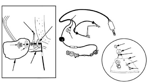
7. Referring to Figure 4-86, retie the strain relief plate (3) to the communications cord (1) in
the same manner in which the cord was originally tied.
NOTE
When properly tied, the knot (5) should be between the strain relief plate and the helmet
shell (6).
8. Attach the strain relief plate to the helmet shell using a screw (8), post (4), and spring
washer (7).
9. Referring to Figure 4-86, slide the spacer (10) over the communications cord and the
CEP interface harness and place it near the connector (9). Insert the CEP interface
harness from the outside of the helmet through the hole from which it was previously
removed. Insert the connector into the hole, ensuring that the spacer is against the
helmet and the connector is against the spacer.
10. From inside the helmet, slide the ground lug (11) over the wires and onto the connector,
followed by the nut (12). Ensure that the unattached ground wire (13) is pulled through
the ground lug and nut as shown in Figure 4-86.
11. Ensure that the ground lug is oriented toward the crown of the helmet as shown in
Figure 4-86. Tighten the nut using the 7/16-inch open-end wrench. Ensure that the
nut is tight enough that the ground lug will not rotate when pushed.
12. Using long-nose pliers, carefully bend the ground lug to about a 45-degree angle from
the shell so that it reaches the unconnected ground wire. Insert the stripped end of the
unconnected ground wire through the small hole at the end of the ground lug. Wrap the
exposed part of the wire once around the end of the ground lug. Solder the wire. Bend
the ground lug flush with the inside surface of the helmet shell.
Figure 4-86. Communications Assembly
10
11
12
9
13
OUTSIDE OF HELMET
1
2
3
4
3
5
6
7
8
Change 3
4-64.5
TM 1-8415-216-12&P