13. Insert the communications cord leads from the outside of the earcup through the holes
from which they were previously removed and seat the grommets.
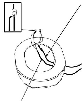
14. From outside the earcup, insert the interface harness into the hole from which it was
previously removed and seat the grommet. (See Figure 4-87.) Pull additional wire
through the grommet into the earcup to make soldering connections easier.
15. Using long-nosed pliers, bend
the stripped end of the inter-
face harness into a hook and fit
the hook around the exposed
wire of the black communica-
tions cord lead as shown in the
attachment detail in Figure
4-87.
CAUTION
In Step 16, use only rosin core
solder when soldering the
wires.
16. Solder the hook and the
exposed wire to form a single
junction.
17. Repeat Steps 14 through 16 to
connect the white lead of the
interface harness to the white
lead of the communications
cord.
NOTE
The receiver is not polarized.
In Step 18, the white and black
leads can be attached to the
receiver either way.
18. Insert the communications cord
leads into the receiver and
tighten the set screws.
19. Insert the cushion, ear lengthwise into the shell, earphone. Center it in the shell,
ensuring that the receiver and the communications cord leads are accessible.
20. Center the receiver in front of the cushion, ear. Insert the receiver retainer into the
earcup and center it so that the receiver is seated in the receiver pocket.
Figure 4-87. Interface Harness Connected to
Communications Cord
ATTACHMENT
DETAIL
INTERFACE HARNESS
COMMUNICATIONS CORD
4-64.6 Change 3
TM 1-8415-216-12&P


