TM 1-8415-216-12&P
g. Installing V-1 ANVIS mount on dual visor assembly.
INITIAL SETUP
Tools/Equipment
Screwdriver, cross-tip (XTS-100)
Jeweler’s screwdriver set (CM3033)
Personnel Required
ALSE Specialist/Technician
or Personnel with ASI of
H2/Q2 (ALSE Qualified)
Materials/Parts
Dual visor assembly (1680-ALSE-200-1)
V-1 ANVIS mount (5002530)
Hardware Kit, Mech. (1680-ALSE-292)
1.
2.
3.
4.
5.
6.
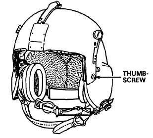
Remove four thumb-
screws that attach visor
assembly to helmet;
remove visor assembly
(refer to Figure 4-65).
Remove thumbscrews
from visor assembly.
Remove housing from
tracks.
Remove four screws on
the back of the ANVIS
mount.
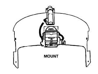
Referring to Figure
4-66, place the mount
against the front of the
visor housing and align
the mount holes with
the visor housing holes.
Attach the mount to
the housing by inserting
four #4-40 x 3/16” pan-
head screws (supplied
in the hardware kit,
mech.) through the
back of the housing and
into the mount. Fasten
the screws securely,
but do not overtighten.
Figure 4-65. Visor Assembly
Figure 4-66. ANVIS Mount Attached to Housing
4-59


