TM 1-8415-216-12&P
7.
8.
9.
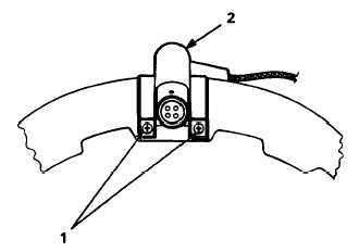
Referring to Figure 4-67, remove
two screws (1), washers, and
posts attaching the fairlead, block
and the cover, access (2) to the
visor housing.
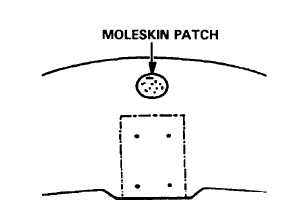
Referring to Figure 4-68, remove
the moleskin patch covering the
cover, access retaining screw on
the inside of the visor housing.
Remove the cover, access from
the housing by removing the re-
taining screw from which you re-
moved the moleskin patch.
Figure 4-67. Cover, Access
10. Route the cable and the connec-
tor under the cover, access.
CAUTION
When reinstalling the cover, access, be
careful to install the screws just snugly
enough to secure the cover. Tightening
the screws too much may damage the
cover.
Figure 4-68. Moleskin Patch Covering Screw
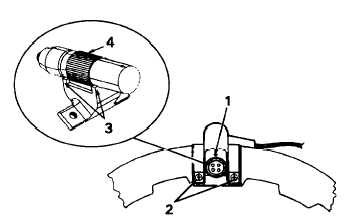
block.
11. Referring to Figure 4-69,
reattach the cover, access and
the fairlead, block to the visor
housing with the screws (2),
washers, and posts removed in
Step 8. Ensure that the red
dot (1) on the connector points
up and that the knurls (4) on
the connector are seated be-
tween the ridges (3) on the
Figure 4-69. Reinstalling Cover, Access
4-60


