TM 1-1510-225-10
3C-28
feet or deviates more than 1000 feet from the selected
altitude.
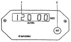
1.
Selected Altitude Display
2.
Altitude Selector Knob
Figure 3C-13. Altitude Select Controller
(2) The altitude is selected by turning the
selector knob until the altitude display reads the
desired value. No further action is taken on the
controller. To initiate altitude pre-select, the ALTSEL
button is selected on the flight director controller. The
pilot must initiate a maneuver to fly toward the pre-
selected altitude. Any of the following pitch modes
may be engaged: Pitch Hold, Airspeed Hold or Vertical
Speed Hold. Upon initiation of altitude pre-select
capture, the previously selected pitch mode is
automatically reset.
3C-20. AUTOPILOT CONTROLLER.
a. Description. The autopilot provides the
means of engaging the autopilot and yaw damper, as
well as manually controlling the autopilot through the
turn knob and pitch wheel. The autopilot system limits
are provided in the Autopilot System Limits Table.
Refer to Table 3C-1.
(1) Pitch Wheel. Movement of the pitch
wheel will cancel only ALT HOLD and ALTSEL CAP.
With vertical modes of VS or IAS selected on the
mode selector, rotation of the pitch wheel will change
the respective displayed vertical mode reference. VS
or IAS mode may be canceled by pressing the mode
button on the mode selector. If VS or IAS is not
selected, the pitch wheel works as described above.
The pitch wheel is always disabled during a coupled
glideslope. Refer to Figure 3C-14.
(2) Bank Limit. Selection of the bank limit
mode on the autopilot controller provides a lower
maximum bank angle while in the HDG mode. LOW
will illuminate on the BANK LIMIT switch. The lower
bank limit is inhibited and LOW is extinguished during
NAV mode captures. If HDG is again engaged, BANK
LIMIT will again be illuminated. Pressing BANK LIMIT
when illuminated will return autopilot to normal bank
limits.
(3) SOFTRIDE
Push
Button.
Softride
reduces autopilot gains while still maintaining stability
in rough air. This mode may be used with any FD
mode selected.
(4) TURN Knob. Rotating the TURN knob
out of detent results in a roll command. The roll angle
is proportional to, and in the direction of, the TURN
knob rotation, the turn knob must be in detent (center
position) before the autopilot can be engaged.
Rotating the turn knob cancels any other previously
selected lateral mode.
(5) YD ENGAGE Push Button. When the
autopilot is not engaged, the yaw damper may be
utilized by pressing the YD ENGAGE push button.
Table 3C-1. Autopilot System Limits
MODE
CONTROL OR SENSOR
PARAMETER
VALUE
Yaw Damper
Yaw Control
Engage Limit
Unlimited
AP Engage
Engage Limit
Roll Up to ± 90°
Pitch Up to ± 30°
Basic AP
Touch Control Steering TCS
Roll Control Limit
Up to ± 45° Roll
Up to ± 25° Pitch
Turn Knob
Roll Angle Limit
Roll Rate Limit
± 30°
± 15°/sec
Pitch Wheel
Pitch Angle Limit
± 15° Pitch
Heading Hold
Roll Angle Limit
Less than 6° and no roll
mode selected.


