TM 1-1510-225-10
3C-24
director/air data system that has a full complement of
horizontal and vertical flight guidance modes. These
include all radio guidance modes, and air data oriented
vertical modes.
When engaged and coupled to the flight director
commands, the system will control the aircraft using
the same commands displayed on the attitude director
indicator. When engaged and uncoupled from the
flight director commands, manual pitch and roll
commands may be inserted using the Touch Control
Steering (TCS) or the pitch wheel and turn knob.
System limits are shown in Table 3C-1.
When the autopilot is coupled, the flight director
instruments
act
as
a
means
to
monitor
the
performance of the autopilot. When the autopilot is not
engaged, the same modes of operation are available
for flight director only. The pilot maneuvers the aircraft
to satisfy the FD commands, as does the autopilot
when it is engaged.
NOTE
The
autopilot
will
disengage
when
transferring between the pilot and copilot
flight directors.
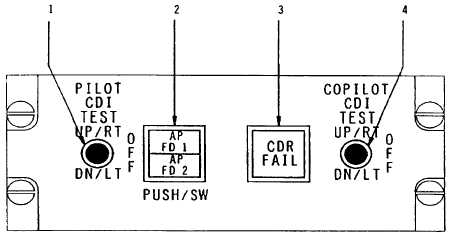
b. Autopilot Flight Director Transfer Panel.
Refer to Figure 3C-11. A panel containing an alternate
action autopilot and flight director transfer switch,
placarded AP FD 1 and AP FD 2, is located on the
pedestal extension. This switch is used to select
which autopilot flight director computer controls the
aircraft flight servos. If AP FD 2 is selected, the
annunciators placarded AP FLT DIR NO. 2, located
above the pilot's and copilot's ADI's, will illuminate to
alert both pilots that the No. 2 autopilot flight director
computer is controlling the aircraft. The NO. 1 AP FD
is not annunciated.
NOTE
If VOR is selected on both the pilot and
copilot HSI's, the DME readout and Radar
NAV display will accompany the selected
autopilot flight director.
c. Air Data Computer. A digital air data
computer,
located
in
the
forward
avionics
compartment, provides the altitude information for the
pilots' servoed altimeter, altitude alerter, flight data
recorder, and transponder. The computer also
provides altitude and airspeed hold function data to the
flight control computers, generates and provides total
airspeed, static/total air temperature to the TAS / SAT
/TAT
indicator
with
inputs
from
the
airspeed/
temperature probe. The air data computer receives 28
Vdc power through, and is protected by, a 2-ampere
circuit breaker, placarded AIR DATA ENCODER,
located in the avionics section of the circuit breaker
panel. All air data computer functions are automatic in
nature and require no flight crew action.
1. Pilot’s CDI Failure Warning Test Switch
2. AP Flight Director Transfer Switch
3. Crash Data Recorder Fail Light
4. Copilot’s CDI Failure Warning Test Switch
Figure 3C-11. Autopilot/Flight Director Transfer Panel