TM 1-1510-225-10
3C-25
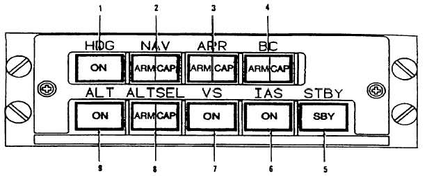
d. Flight Director/Mode Selector. Refer to
Figure 3C-12. This provides all mode selection,
except go-around that is initiated by a remote switch,
for the flight director. The top row of light annunciated
push buttons contains the lateral modes and the
bottom row contains the vertical modes. The split light
push buttons illuminate yellow for armed conditions
and green for captured. When more than one lateral
or vertical mode is selected, the flight director system
automatically arms and captures the submode. The
mode annunciations are repeated on the remote
annunciator blocks above both ADI's, with the addition
of GS ARM, GS CAP, AP ENG, YD ENG and GA.
(1) Heading Mode Selector. The Heading
Select Mode is selected by pressing the HDG button
on the mode selector. The HDG annunciator
illuminates. In the HDG mode, the flight director
computer provides inputs to the command cue to
command a turn to the heading indicated by the
heading bug on the HSI. The heading select signal is
gain programmed as a function of airspeed. When
HDG is selected, it overrides the Nav, BC APR and
VOR APR modes. In the event of a loss of valid signal
from the VS or compass, the command cue is biased
out of view.
(2) Navigation (NAV) Mode Selector. The
NAV represents a family of modes for various
navigation systems including VOR, Localizer, TACAN
or VLF as selected by the HSI selector switches.
(a) VOR Mode. The VOR Mode is
selected by pressing the NAV button on the mode
selector with the navigation receiver tuned to a VOR
frequency and DME greater than 20 miles from the
station. Prior to VOR capture, the command cue
receives a heading select command, as described
above, and the HDG mode annunciator on the mode
selector is illuminated along with the NAV ARM
annunciator on the mode selector. Upon VOR
capture, the system automatically switches to the VOR
mode HDG and NAV ARM annunciators extinguish
and NAV capture NAV CAP annunciator on the mode
selector will illuminate. At capture, a command is
generated to capture and track the VOR beam. VOR
deviation is gain programmed as a function of distance
from the station. This programming corrects for beam
convergence thus optimizing the gain through the
useful VOR range. To utilize this feature, the DME
must be tuned to the same VOR station as the NAV
receiver, which is feeding the flight director. The
course error signal is gain programmed as a function
of airspeed. Crosswind washout is included, which
maintains the aircraft on beam center in the presence
of crosswind. The intercept angle and DME distance
are used in determining the capture point to ensure
smooth
and
comfortable
performance
during
bracketing.
1. Heading Mode Selector
2. Navigation Mode Selector
3. Approach Mode Selector
4. Backcourse Mode Selector
5. Standby Mode Selector
6. IAS Mode Selector
7. VERT Speed Mode Selector
8. ALT Pre-Select Mode Selector
9. ALT Hold Mode Selector
Figure 3C-12. Flight Director/Mode Selector


