TM 1-1510-225-10
3B-75
Table 3B-28. Navigation Configuration Page
NO.
DESCRIPTION/FUNCTION
1
Select Index page (IDX ).
2
Select Navigation Configuration page.
3
Indication of designated pilot selection
(always PILOT).
4
Entered Flight Plan Bank Limit.
5
Scroll
vertically
to
access
more
configuration pages.
6
Entered Speed deviation alert threshold
(knots).
7
Entered
ground
speed
default
for
calculations while on the ground.
8
Entered waypoint alert time in seconds
prior to waypoint arrival or leg switch.
9
Entered
cross
track
deviation
alert
threshold (nautical miles).
10
Flight
instruments
scaling
mode
selection:
OCEANIC,
EN
ROUTE,
TERMINAL, or APPROACH.
(c) Entry and Use of Waypoint Wind. On
the Flight Plan Waypoint page, a predicted wind can
be entered for each waypoint in the flight plan. Refer
to Figure 3B-38 and Table 3B-29. Wind entries are
used with current True Airspeed to provide improved
prediction for waypoint ETA and ETE as shown on the
Lateral Steer page, Figure 3B-36.
When wind is entered at a future waypoint, the
wind entry will be fixed at the entry waypoint and
propagate through the flight plan to all subsequent
waypoints. When new waypoints are inserted into the
flight plan, the default wind for the new waypoint will
be based on the previous waypoint’s wind entry.
When no wind entry is provided, the FMS uses current
wind for predicted arrivals at the waypoint. The active
waypoint wind will show the current wind conditions
and entry is not permitted. The wind for history
waypoints is the actual wind measured at waypoint
passage, and entry is not permitted. Wind direction is
entered in the direction from which the wind is blowing.
When transferring a flight plan from the alternate
to the active flight plan, the waypoint wind entered in
the alternate flight plan will be retained in the active
flight plan definition.
(d) Control
and
Display
of
Bank
Command Limits and Crosstrack Deviation Alerting.
The bank command limit for the FMS steering and
flight plan leg switching is controlled by the crew
entering a value on the Navigation Configuration page.
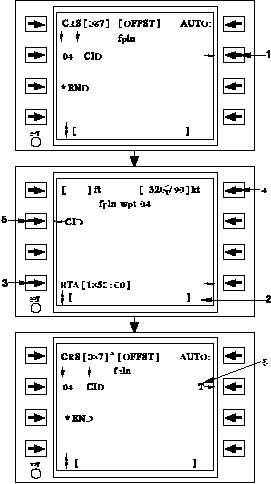
Figure 3B-38. Flight Plan Waypoint Page
Table 3B-29. Flight Plan Waypoint Page
NO.
DESCRIPTION/FUNCTION
1
Access Flight Plan Waypoint page.
2
Enter RTA into the scratchpad.
3
Select RTA line select key to insert RTA.
4
Entered wind for future legs (defaults to
computed wind for current leg).
5
Return to the Flight Plan page.
6
T indicates RTA assigned to the waypoint.
Entering a – and pressing this line select
key will delete the RTA at this waypoint.


