TM 1-1510-225-10
3A-65
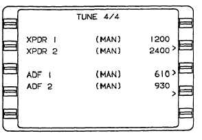
(4) Tune 4/4 Page, XPDR / ADF. Refer to
Figure 3A-46.
Figure 3A-46. Tune 4/4 Page, XPDR/ADF
(a) XPDR. This field displays the
transponder (XPDR) reply code. The transponder
reply code will appear briefly but will turn to dashes
because the system interface does not provide a
return frequency input. MAN indicates the entry was
made through the control unit.
NOTE
If either the XPDR or ADF frequencies are
tuned via the keyboard, MAN will not
appear.
(b) ADF.
This
field
displays
the
Automatic Direction Finder (ADF) frequency. The ADF
frequency will appear briefly but will turn to dashes
because the system interface does not provide a
return frequency input. MAN indicates the entry was
made through the control unit.
m. Holding Pattern Section (HOLD Key).
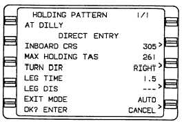
(1) Holding Pattern 1/1 Page. Refer to
Figure 3A-47. This page is accessed by pressing the
HOLD key when the cursor is positioned over a
waypoint identifier.
(a) AT. This line displays the holding fix
and country name or airport ident.
Figure 3A-47. Holding Pattern 1/1 Page
(b) Holding Pattern Entry And Status
Message. If the entry course to the holding fix can be
determined, the entry procedure will be annunciated
after all the holding pattern parameters are entered.
1 DIRECT ENTRY. This indicates
that the system will use a direct entry to the holding
pattern.
2 TEARDROP
ENTRY.
This
indicates that the system will use a teardrop entry to
the holding pattern.
3 PARALLEL ENTRY – Indicates
that the system will use a parallel entry to the holding
pattern.
4 HOLDING – Indicates that the
system has entered the holding pattern.
5 EXIT HOLD – Indicates that the
system will exit the holding pattern the next time over
the holding fix.
(c) INBOUND CRS. This field displays
the inbound course (INBOUND CRS) in degrees. This
field can be indexed to true north or magnetic north
depending upon the display mode selected by the
TRUE/MAG switch input. A T appears if the system is
in the true mode.
(d) MAX HOLDING TAS. The maximum
holding true airspeed field (MAX HOLDING TAS) is
computed based on configuration module maximum
holding indicated airspeed and worst case winds. It
represents the maximum true airspeed in the holding
pattern that will assure that the aircraft remains in
protected airspace.
(e) TURN DIR. The turn direction
(TURN DIR) field indicates the direction of turns in the
holding pattern. RIGHT displayed in this field indicates


