TM 1-1510-218-10
3A-41
6. Vary
the
TILT
control
manually
between 0 and up 15° and observe
that close in “ground clutter” appears
at lower settings and that any local
rain appears at higher settings.
7. Repeat the manual tilt adjustment, this
time between the 0 and down 15°
positions.
8. Function switch – Return to TST or
SBY before taxiing.
9. Function switch, before or after takeoff
– ON and operate as required.
3A-30. RADAR GRAPHICS.
a. Description. The KGR-358 radar graphics
unit
interfaces
with
the
weather
radar
system
(RDR 2000), and receives navigation data from the
flight management system, KLN 90B. Refer to Figure
3A-24. The unit can display NAV 1 or NAV 2 or both
in a weather overlay, or as navigation information only
display. In addition, NAV information can be viewed in
a 360° (circle) display with weather in the top 90°
sector. Two checklist modes are also provided for
complete checklist capability when utilizing the pocket
terminal.
With the KGR-358 in any of the NAV modes, the
radar screen will display a normal weather picture plus
the location of the waypoints listed in the active flight
plan. Data referenced to NAV 1 is displayed in the
lower left portion of the radar display. Data referenced
to NAV 2 will display in the lower right portion of the
display. Included in the data are the active waypoint
name, the selected course bearing, and the aircraft
position (radial to, and distance) from the active
navigation fix. Aircraft magnetic heading is displayed
in the upper left section of the radar display.
A line representing the course selected by the
flight management system is drawn through the
corresponding active waypoint. Selected course
bearing for each NAV system is displayed with NAV
data on each side of the screen. A waypoint line will
also be displayed connecting the waypoints in
numerical sequence. An R on the left side of the
screen indicates all visible NAV aids selected by the
flight management system will be displayed. The level
of NAV aids displayed is indicated by one, two, or
three dots on the left side of the R.
A joystick control is provided to move a waypoint
to any position on the screen. The coordinates for this
new waypoint will appear in the lower left or right
corner depending upon which NAV is selected
replacing the active waypoint data. If both NAV
systems are selected, the new coordinates will be
displayed corresponding to NAV 1, and may be
switched to NAV 2. Pressing the check button will
cause the data to transfer to the flight management
system and be fixed as a position on the earth. Once
the data is transferred to the flight management
system, the pilot may enter it, as he desires.
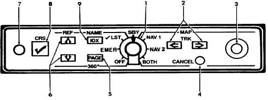
1. Mode Selector Knob
2. Left / Right Cursor Buttons
3. Joystick
4. CANCEL Button
5. PAGE Button
6. Up / Down Cursor Button
7. Input Jack
8. Checklist Button
9. Index Button
Figure 3A-24. Radar Graphics
A track line enables a quick determination of how
many degrees deviation left or right of a present
heading is needed to provide for a clear path through
weather or to a new fix. The number of degrees and a
L or R is shown in the upper left corner replacing the
magnetic heading when track mode is in operation.