TM 1-1510-218-10
3A-40
NOTE
A TX FLT is indicated if the Strut switch is
configured to be active and the aircraft is
on the ground.
Table 3A-3. Hard Failure Annunciations
ANNUNCIATION
FAILURE
TX FLT
Transmitter failure
429FLT
Loss of 429 bus data
ANT FLT
Loss of antenna position
IN FLT 6
Loss of communication
between
display
and
ART
Soft failures are those that can cause limited
system operation. Radar data will still be displayed,
but the flight crew should be aware that the display
does not necessarily represent the true weather. Soft
failures
are
typically
configuration
problems,
stabilization problems, or some similar problem. Refer
to Table 3A -4 for soft failure annunciations.
Table 3A-4. Soft Failure Annunciations
ANNUNCIATION
FAILURE
TX FLT
Configuration module not
being read
STAB LMT
Stab is exceeding ±30°
STAB OFF
Alert that the scan is not
being stabilized
d. Weather Radar System Operation.
Never operate the weather radar in the Wx,
WxA, LOG or GND MAP modes on the
ground when personnel are forward of the
aircraft wing and within 5 feet of the
aircraft nose. Failure to observe this
warning may result in permanent damage
to the eyes and other body organs of those
persons.
Never turn the radar on within 5 feet of
containers of flammable or explosive
material. Never operate radar during
fueling operations.
NOTE
These procedures should be accomplished
prior to flight.
(1) Accomplish
the
following
procedure
completely and exactly.
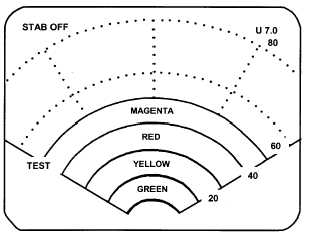
1. Function switch – TST.
2. TILT – UP 7.0, as shown on the
indicator display, upper right corner.
The test pattern will appear. See that the test
pattern conforms to the illustration. Refer to Figure
3A-23. The test pattern is sized to fit the 80 nm range
and can be scaled with the range buttons, and observe
the “update” action as a small ripple moves across the
display along the outer edge.
Figure 3A-23. Test Pattern
With the function switch in TST or SBY, taxi to a
clear area where there are no people, aircraft,
vehicles, or metallic buildings within approximately
100 yards.
3. Function switch – ON.
The indicator will automatically display in the Wx
mode and 80-nm range. Any targets, weather or
ground, will be displayed in green, yellow, red, or
magenta.
NOTE
A 60-second warm-up time period is
required before the system will transmit.
4. RNG ¬ button – Press to display
40 nm as the maximum range.
5. WxA button – Press and observe the
magenta areas (if any) flash.
WARNING