TM 1-1510-218-10
3A-25
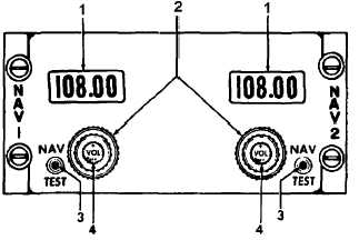
1. Frequency Indicator
2. Frequency Control
3. NAV TEST Push Button
4. VOL OFF Control
Figure 3A-14. VOR Control Panel
d. Operation.
(1) Turn-On Procedure.
1. VOL / OFF control – Turn clockwise.
(2) Operating Procedure.
1. Frequency selectors – Set desired
frequency.
2. VOL control – As required.
3. Determine
course
to
station
on
horizontal situation indicator. Refer to
Figure 3A-8 or 3A -9.
a. VOR 1 / VOR 2 switch – As
required.
b. Course knob – Rotate knob until
course deviation bar is centered
and to-from arrow indicates TO.
c. Course readout – Read bearing to
station.
4. Determine course to station on RMI.
Refer to Figure 3A-7.
a. Single or double needle pointer
switches – As required, depending
upon whether VOR 1 or VOR 2 is
in use.
b. Single or double needle on RMI –
Read course to station.
(3) Localizer Receiver Operating Procedure.
1. Frequency selectors – Set required
frequency.
2. VOR 1 / VOR 2 switch – As required.
3. Course deviation indicator – Steer
aircraft as required to center course
deviation bar.
(4) Marker Beacon Operating Procedure.
1. Marker beacon indicator lights (Figure
2-17) – Observe for beacon indication.
2. MKR BCN HI / LO sensitivity switch
(Figure 3A -1) – As required.
3. MKR BCN VOL control (Figure 3A-1)
– As required.
(5) Glideslope Operating Procedure.
1. Frequency selectors – Set desired
localizer frequency.
2. VOR 1 / VOR 2 switch (Figure 2-17) –
As required.
3. Glideslope pointer (Figure 3A-9) –
Steer aircraft as required to center
pointer.
(6) VHF
Communications
Receiver
Operating Procedure.
1. Frequency selectors – Set desired
frequency.
2. VOL control – As required.
(7) Shutdown Procedure.
1. VOL
/
OFF
control
–
Turn
counterclockwise.
3A-23. ADF RADIO SETS (DF-203).
a. Description. Two ADF radio sets are
installed. The units are airborne low frequency radio
direction finders that receive signals from transmitters
in the 190 to 1750 kHz range to provide a visual and
aural indication of the aircraft's bearing in relation to
the transmitter. The set can also be used for homing