TM 1-1510-218-10
3A-30
3A-25. DISTANCE
MEASURING
EQUIPMENT
SYSTEM (DME-40).
a. Description. The DME system measures the
slant range, line-of-sight, distance from the aircraft to a
ground station and displays a continuous distance
readout in nautical miles. The system also displays
aircraft groundspeed in knots or time-t o-station in
minutes. The groundspeed and time-to-station are
accurate only if the aircraft is flying directly toward the
ground station at a sufficient distance that the slant
range and ground range are nearly equal. The DME
system is protected by a 2 -ampere circuit breaker,
placarded DME, on the overhead circuit breaker panel.
b. Controls and Functions, DME Control
Panel. Refer to Figure 3A-17.
(1) DME SEL Switch. Controls operation of
the system.
(a) STBY. Places system in standby.
(b) VOR-1. Allows channel selection
using frequency controls for VOR-1.
(c) HOLD. System will remain tuned to
previous channel if the VOR is tuned to a new
frequency.
(d) VOR-2. Allows channel selection
using frequency controls for VOR-2.
(2) VOL Control. Controls volume.
1. DME SEL Switch
2. VOL Control
Figure 3A-17. DME Control Panel
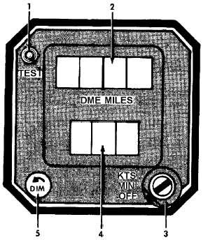
c. Controls/Indicators and Functions, DME
Indicator. Refer to Figure 3A-18.
1. TEST Push Button
2. DME MILES Indicator
3. Control Switch
4. Knots / Minutes Display
5. DIM Control
Figure 3A-18. DME Indicator
(1) TEST Push Button. Initiates self-test of
DME system. When pressed, upper display indicates
0.0 or 0.1 and lower display indicates dashes if control
switch is in MIN position or 888 when in the KTS
position.
(2) DME MILES Indicator. Digital display of
slant-range distance from aircraft to ground station in
nautical miles.
(3) Control Switch. Controls operation of the
DME system.
(a) OFF. Turns system off.
(b) MIN. Selects time-to-station in
minutes for display on bottom readout.
(c) KTS. Selects aircraft groundspeed in
knots for display on bottom readout.