TM 1-1510-218-10
3A-33
(2) Pitch Control Thumbwheel. Supplies
pitch rate commands to autopilot. Spring loaded to
center detent.
e. Controls and Functions, Control Wheel
Switch.
(1) DISC-TRIM / AP YD Push Button. When
pressed to first detent, autopilot system and yaw damp
are disconnected. When pressed to second detent,
electric trim is disconnected.
(2) PITCH SYNC & CWS Push Button. This
button on the control wheels may be used instead of
the pitch/turn control to establish the aircraft in a
desired attitude. Pressing the button causes the
autopilot servos to disengage from the control
surfaces, enabling the pilot to manually fly the aircraft
to the desired attitude until button is released.
f. Controls
and
Functions,
GO-AROUND
Switch.
(1) GO AROUND Switch. Located on the
outboard side of left power lever. When pressed,
activates the go-around mode of flight director. GA
light illuminates on autopilot/flight director annunciator
panel, the autopilot is disengaged, and the pilot's
horizon reference indicator gives command for wings
level and 70 nose up climb attitude.
g. Autopilot/Flight
Director
Annunciator
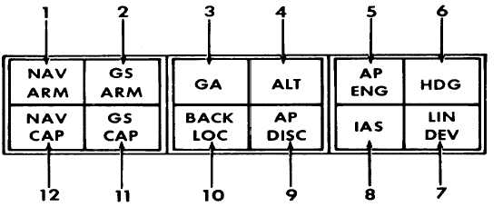
Panel Indicators and Functions. Refer to Figure
3A-21. The autopilot/flight director incorporates its
own annunciator panel located just above the flight
director display on the instrument panel. The modes
and indications given on the annunciator panel are
placarded on the face of the lenses and illuminate
when
the
respective
conditions
are
indicated.
Dimming of the annunciator panel lights is provided by
a switch adjacent to the panel placarded DIM / BRT.
(1) NAV ARM Indicator. Illuminates when
computer is armed to accept navigation signals.
(2) GS ARM Indicator. Illuminates when
approach mode is selected prior to glideslope capture.
Extinguishes after glideslope capture.
(3) GA Indicator. Illuminates when go-
around mode is selected.
(4) ALT Indicator. Illuminates when altitude
hold mode is selected.
(5) AP ENG Indicator. Illuminates when
autopilot is disengaged.
1. NAV ARM Indicator
2. GS ARM Indicator
3. GA Indicator
4. ALT Indicator
5. AP ENG Indicator
6. HDG Indicator
7. LIN DEV Indicator
8. IAS Indicator
9. AP DISC Indicator
10. BACK LOC Indicator
11. GS CAP Indicator
12. NAV CAP Indicator
Figure 3A-21. Autopilot / Flight Director Annunciator Panel
(6) HDG Indicator. Illuminates when heading
mode is selected.
(7) LIN DEV Indicator. Illuminates when
distance and bearing data is received from VORTAC
and DME is valid.


