TM 1-1510-218-10
3A-23
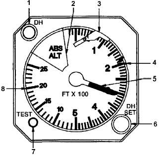
1. Decision Height Annunciator
2. Pointer Mask
3. Failure Warning Flag
4. Decision Height Marker
5. Altitude Pointer
6. Decision Height Set Knob
7. Test Switch
8. Altitude Scale
Figure 3A-13. Radio Altimeter (RA-315)
(2) Pointer
Mask. The pointer mask,
placarded ABS ALT, covers the pointer for altitudes
above 2500 feet.
(3) Failure Warning Flag. A flag, placarded
OFF, will be in view whenever the radio altimeter
system information is unreliable.
(4) Decision Height Marker. The decision
height marker is set to the desired decision height by
the DH SET knob.
(5) Altitude Pointer. The altitude pointer
indicates altitude above ground or surface level.
(6) Decision Height Set Knob. A knob,
placarded DH SET, located on the lower right corner of
the radar altimeter indicator, is used to set the orange
decision height marker to the desired DH.
(7) Test Switch. A momentary push-button
switch, placarded TEST, located on the lower left
corner of the radio altimeter indicator, is used to
activate the unit's self test function. When the switch
is pressed, the OFF warning flag will come into view
and the altitude pointer will indicate approximately 100
+20 feet. Releasing the switch will cause the altitude
pointer to return to existing altitude, and OFF warning
flag to retract from view.
(8) Altitude Scale. Indicates altitude of
aircraft.
3A-21. GYROMAGNETIC COMPASS SYSTEMS.
a. Description.
Dual
identical
compass
systems provide accurate directional information for
the aircraft at all latitudes of the earth. As a heading
reference,
two
modes
of
operation
are
used,
directional gyro (FREE) mode or slaved (SLAVE)
mode. In Polar Regions of the earth where magnetic
heading references are not reliable, the system is
operated in the FREE mode. In this mode, the system
furnishes an inertial heading reference, with latitude
corrections introduced manually. In areas where
magnetic heading references are reliable, the system
is operated in the SLAVE mode. In this mode, the
directional gyro is slaved to the magnetic azimuth
detector, which supplies long-term magnetic reference
for correction of the apparent drift of the gyro.
Magnetic heading information from both systems is
applied to various aircraft systems through pilot and
copilot's COMPASS switches. There are no front
panel fuses or circuit breakers for the gyromagnetic
compass systems.
b. Controls and Functions. Refer to Figure
2-17, Sheet 1.
(1) Pilot's COMPASS # 1 / # 2 Switch.
Selects
desired
source
for
magnetic
heading
information for display on pilot's HSI copilot's RMI.
(a) # 1. Selects compass system No. 1
for display.
(b) # 2. Selects compass system No. 2
for display.
(2) Copilot's COMPASS # 1 / # 2 Switch.
Selects
desired
source
for
magnetic
heading
information for display on copilot's HSI and pilots RMI.
(a) # 1. Selects compass system No. 1
for display.
(b) # 2. Selects compass system No. 2
for display.
(3) COMPASS
SLAVE
Annunciator.
Presents a visual indication of system synchronization
operation.