TM 1-1510-218-10
3A-19
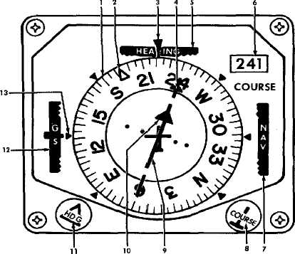
1. Compass Card
2. Heading Marker
3. Lubber Line
4. Course Arrow
5. HEADING Flag
6. COURSE Indicator
7. NAV Flag
8. COURSE Control
9. Course Deviation Bar
10. To-From Arrow
11. HDG Control
12. GS Flag
13. Glideslope Pointer
Figure 3A-8. Pilot’s Horizontal Situation Indicator
(1) Copilot's VOR 1 / 2 Switch. Controls
course select and display circuits of the HSI.
(a) VOR 1. Circuits are connected to
VOR No. 1 receiver.
(b) VOR 2. Circuits are connected to
VOR No. 2 receiver.
(2) Copilot's COMPASS # 1 / # 2 Switch.
Selects
desired
source
for
magnetic
heading
information for display on compass card of indicator.
c. Copilot’s Horizontal Situation Indicator.
Refer to Figure 3A-9.
(1) Heading Marker. Positioned by HDG
knob to selected heading.
(2) COMPASS Flag. Indicates loss of
reliable heading information.
(3) Lubber Line. Indicates heading of
aircraft.
(4) Course Arrow. Positioned by COURSE
knob to selected VOR radial.
(5) Compass
Card.
Indicates
aircraft
magnetic heading supplied by system selected on
copilot's COMPASS # 1 / # 2 switch.
(6) COURSE Indicator. Presents a digital
readout of course selected by the COURSE knob.
(7) VOR LOC Flag. Indicates loss of or
unreliable navigation signal.
(8) COURSE Control Knob. Used to select
desired VOR course.
(9) Course Deviation Bar. Indicates lateral
course deviation selected by the copilot's VOR 1 / 2
switch.