MWO 1-8415-216-20-1
NOTE
In step (i) below, ensure that the soldering is performed by qualified personnel,
and in accordance with ANSI/J-STD-001.
(j) Repeat steps (f)-(i) above, to connect the white lead of the interface harness to
the white lead of the communications cord.
NOTE
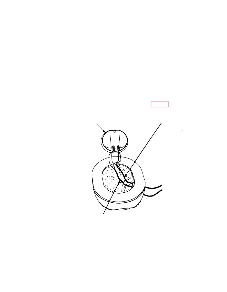
The receiver is not polarized. In step (k) below, the white and black leads can
be attached to the receiver either way.
completed connection.
COMMUNICATIONS CORD
RECEIVER
/
/
1
INTERFACE HARNESS
Figure 10. Earcup Reassembly
(I) From outside the earcup, carefully pull the excess wire from the communications
cord and the interface harness back through the grommets, being careful not to pull the CEP
interface cable beyond the point at which the shrink tubing touches the grommet.
13


