MWO 1-8415-216-20-1
harness and onto the connector.
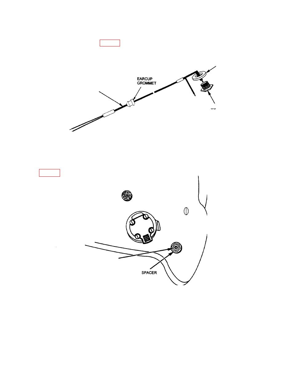
SPACER
INTERFACE
HARNESS
CONNECTOR
Figure 4. CEP Interface Harness.
(q) From outside the helmet, insert the black and white wires of the interface harness
through the drilled hole so that the grommet is completely through hole, the head of the
connector is against the spacer, and the spacer is against the outside of the helmet as shown in
CONNECTOR
-
Figure 5. CEP Connector.
9


