plays (I’s). Since the CLD’s have no BCD decade
counter output; for BCD-DAC decoding, BCD de-
cade counters (DC’s) are added to the display and
counter board for this purpose. LAMP TEST, gener-
ated by the PRESS TO TEST switch, lights all seg-
ments in the displays. RESET, from the A/D con-
verter,
resets the counter-latch-decoders at the
beginning
of the reference integration period.
TRANSFER-TO-MEMORY,
from
the
A/D
con-
verter, transfers the CLD count into the CLD
latches at the conclusion of the reference integra-
tion period to update the display. The blanking
TM 55-4920-401-13&P
input of the CLD’s is controlled by FF2B (fig. 1-3)
and goes high to blank an indicator display on every
other reading when the input signal to the indicator
is out-of-range.
(2) Temperature Indicator. The following
subparagraphs describe circuitry that is unique to
the temperature indicator.
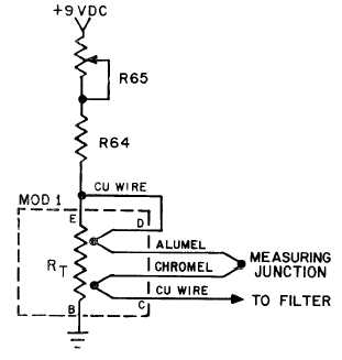
( a ) T e m p e r a t u r e S i g n a l C o n d i-
tioning. A thermocouple circuit is formed when
the thermocouple wire of the measuring junction is
connected to the copper wiring of the A/D converter
at the Compensator (fig. 1-13). The junction at the
Figure 1-13. Temperature Indicator Compensator.
compensator is called the reference junction. Any
RT. The negative thermocouple lead is connected
variation in the temperature of the reference junc-
tion will cause either an increase or decrease in the
signal voltage. To measure temperature accurately,
the reference junction must either be held at a con-
stant temperature or referenced to a voltage which
varies with temperature and in relation to the ther-
mocouple curve. The compensator generates a refer-
ence voltage through the use of a thermal resistor,
with copper wire to the higher potential end of this
resistor. The thermal resistor, having a positive
temperature coefficient, modifies the reference
voltage when the ambient temperature increases.
To assure that their temperatures are the same, the
reference junction and thermal resistor are
encapsulated.
1-12