TM 55-1510-219-10
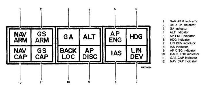
(d) Autopilot/flight director annunciator
panel (fig. 3-20). The autopilot/flight director
incorporates its own annunciator panel located just
above the flight director display on the instrument panel.
The modes and indications given on the annunciator
panel are placarded on the face of the lenses and
illuminate when the respective conditions are indicated.
Dimming of the annunciator panel lights is provided by a
switch adjacent to the panel placarded DIM-BRT.
CONTROL/
FUNCTION
INDICATOR
NAV ARM
Illuminates when computer is
indicator
armed to accept navigation sig-
nals.
NAV CAP
VOR-I/TACAN illuminates
indicator
when selected radial is captured.
INS selected, illuminates when
INS is coupled to the flight di-
rector.
GS ARM
Illuminates when approach
indicator
mode is selected prior to glide-
slope capture. Extinguishes after
glideslope capture.
GS CAP
Illuminates when glideslope is
indicator
captured.
GA indicator
Illuminates when go-around
mode is selected.
BACK LOC
Illuminates when back course
indicator
mode is selected.
ALT indicator
Illuminates when altitude hold
mode is selected.
AP DISC
Illuminates when autopilot is
indicator
disengaged.
AP ENG
Illuminates when autopilot is en-
indicator
gaged.
IAS indicator
Illuminates when airspeed hold
mode is selected.
HDG indicator
Illuminates when heading mode
is selected.
LIN DEV
Not Applicable
DIM BRT
Adjusts intensity of illumination
control
of the flight director annunciator
(2)
Pedestal - left power lever (fig. 2-11).
CONTROL/
FUNCTION
INDICATOR
GO AROUND
When pressed, autopilot discon-
switch (outboard
nects, GA annunciator light (fig.
side left power
3-20) illuminates, and horizon
lever)
reference indicator commands
wings level, 7° nose up attitude.
Autopilot may be re-engaged to
follow the command.
Figure 3-20. Autopilot/Flight Director Annunciator Panel
3-36


